


S
Slave Address
R/W
ACK
Data
ACK
Data
ACK
P
7
8
8
1
1
1
1
1
1
Data Line
Stable Data
Change of Data Allowed
SDA
SCL
SDA
SCL
MSB
Acknowledgement
Signal From Receiver
Acknowledgement
Signal From Receiver
1
2
7
8
9
1
2
8
9
ACK
ACK
START
Condition (S)
STOP
Condition (P)
R/W
eUSCI_B Operation – I
2
C Mode
961
SLAU356I – March 2015 – Revised June 2019
Copyright © 2015–2019, Texas Instruments Incorporated
Enhanced Universal Serial Communication Interface (eUSCI) – I
2
C Mode
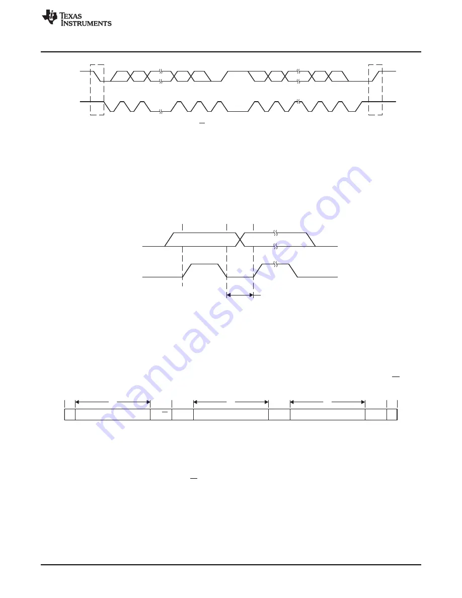
Figure 26-3. I
2
C Module Data Transfer
START and STOP conditions are generated by the master (see
). A START condition is a
high-to-low transition on the SDA line while SCL is high. A STOP condition is a low-to-high transition on
the SDA line while SCL is high. The bus busy bit, UCBBUSY, is set after a START and cleared after a
STOP.
Data on SDA must be stable during the high period of SCL (see
). The high and low state of
SDA can change only when SCL is low, otherwise START or STOP conditions are generated.
Figure 26-4. Bit Transfer on I
2
C Bus
26.3.3 I
2
C Addressing Modes
The I
2
C mode supports 7-bit and 10-bit addressing modes.
26.3.3.1 7-Bit Addressing
In the 7-bit addressing format (see
), the first byte is the 7-bit slave address and the R/W bit.
The ACK bit is sent from the receiver after each byte.
Figure 26-5. I
2
C Module 7-Bit Addressing Format
26.3.3.2 10-Bit Addressing
In the 10-bit addressing format (see
), the first byte is made up of 11110b plus the two MSBs
of the 10-bit slave address and the R/W bit. The ACK bit is sent from the receiver after each byte. The
next byte is the remaining eight bits of the 10-bit slave address, followed by the ACK bit and the 8-bit data.
See
I2C Slave 10-bit Addressing Mode
and
I2C Master 10-bit Addressing Mode
for details how to use the
10-bit addressing mode with the eUSCI_B module.