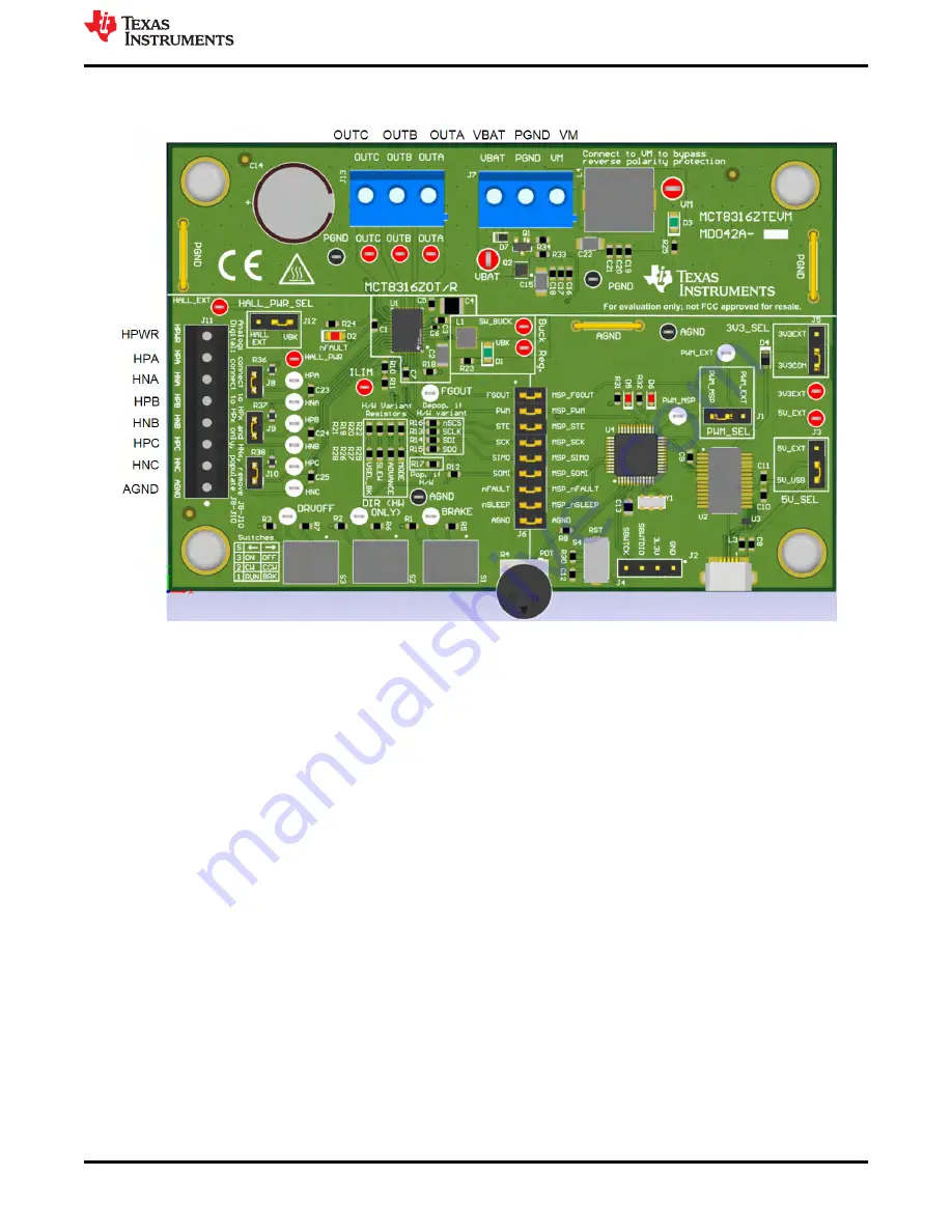
to the HPx and HNx pins for each respective phase and remove jumpers J8-10. Otherwise, if using single-ended
input from a Hall sensor, connect to only the HPx pins for each phase and populate jumpers R8–R10.
Figure 4-2. Connections from Motor to MCT8316ZTEVM
shows where the micro-USB cable is plugged into the MCT8316ZTEVM to provide communication
between evaluation module and GUI. The USB data and 5-V power from the USB is converted into UART data
and 3.3-V power to power the MSP430FR2355 microcontroller. The 5 V from the USB power is limited to 500
mA by the PC and the 3.3 V from the FTDI chip is limit to 30 mA. If the user wishes to supply more current to
these rails, they may use the 5V_SEL jumper J3 and 3V3_SEL jumper J5 to connect external power rails.
Hardware and Software Overview
SNLU291B – MARCH 2021 – REVISED AUGUST 2022
MCT8316ZTEVM Evaluation Module
7
Copyright © 2022 Texas Instruments Incorporated


