background image

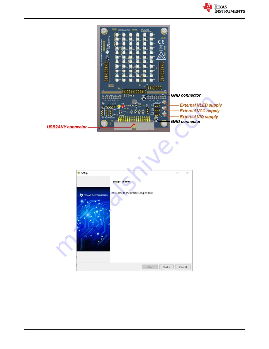
Figure 2-3. Key External Connectors

2.2 Software Setup

Download the LP586x GUI installation package from the 

LP5860 product folder

. Follow the setup wizard to

install the LP586x GUI successfully, see 

Figure 2-4

.

Figure 2-4. GUI Installation

Hardware and Software Preparation

www.ti.com

4

LP5860 Evaluation Module

SNVU762 – MAY 2021

Submit Document Feedback

Copyright © 2021 Texas Instruments Incorporated

Содержание LP5860

Страница 1: ...ces 12 4 1 LP5860EVM Layout 12 4 2 LP5860EVM Schematic 14 4 3 LP5860EVM BOM 15 List of Figures Figure 1 1 LP5860EVM Kit 2 Figure 2 1 Hardware Connection 3 Figure 2 2 Default Jumper Setting 3 Figure 2 3 Key External Connectors 4 Figure 2 4 GUI Installation 4 Figure 3 1 Status Bar 5 Figure 3 2 Firmware Update 5 Figure 3 3 Start Page 5 Figure 3 4 Home Page 6 Figure 3 5 LED Control Page and Test Proce...

Страница 2: ...se the LP5860 GUI to illuminate LEDs Design resources for the LP5860EVM The LP5860EVM kit includes the following materials and is illustrated in Figure 1 1 LP5860 evaluation module USB2ANY interface adapter with ribbon cables and USB cable Full functions for the LP5860 the performance with RGB LED matrix and some simple animation effects can be easily verified through this kit The LP5860EVM can be...

Страница 3: ... port on the computer USB2ANY LP5860EVM USB cable Ribbon Cable Figure 2 1 Hardware Connection Figure 2 2 shows the default jumper settings Figure 2 2 Default Jumper Setting If maximum current is set above 20 mA an external VLED supply is recommended during evaluation since the USB can only provide around 400 mA current The setup procedure follows 1 Connect the USB2ANY to the LP5860EVM using the 30...

Страница 4: ...e from the LP5860 product folder Follow the setup wizard to install the LP586x GUI successfully see Figure 2 4 Figure 2 4 GUI Installation Hardware and Software Preparation www ti com 4 LP5860 Evaluation Module SNVU762 MAY 2021 Submit Document Feedback Copyright 2021 Texas Instruments Incorporated ...

Страница 5: ... the GUI Connection button Connection status Log panel Figure 3 1 Status Bar If the USB2ANY has not been previously used to evaluate the LP5860EVM a correlating firmware FW version must be updated into USB2ANY Following the instructions in the GUI when plugging in the USB cable can update the FW successfully see Figure 3 2 Figure 3 2 Firmware Update 3 1 Start Page Different device variants in the ...

Страница 6: ...d with the PATTERN page while every individual register is configured in the REGISTER MAP page Figure 3 4 Home Page 3 3 LED Control Page Set the color and brightness for every RGB LED pixel in the LED control page To illuminate one LED with default configuration use the following procedure and see Figure 3 5 1 Click the Enable button to enable the LP5860 in the software 2 Select the LED you want t...

Страница 7: ...her settings see the LP5860 11 18 LED Matrix Driver with 8 bit Analog and 8 16 bit PWM Dimming Data Sheet When evaluating matrix issue free performance de ghosting and low brightness compensation are configured here Figure 3 6 Device Configuration Custom LED Setting Before setting color and brightness for RGB LED one or multiple LEDs Shift select for multiple LED selections must first be selected ...

Страница 8: ...are set Figure 3 9 illustrates the GROUP tab where every LED dot can be configured to 3 groups arbitrarily while the PWM for the same group can be changed synchronously Figure 3 8 Global Setting Graphical User Interface GUI Guidance www ti com 8 LP5860 Evaluation Module SNVU762 MAY 2021 Submit Document Feedback Copyright 2021 Texas Instruments Incorporated ...

Страница 9: ...ault status see Figure 3 11 The Clear Short LED and Clear open LED buttons are used to clear related fault flags when the failures are removed To have precise detection results the current for every LED dot must be set above 0 5 mA and the PWM must be set above 25 due to the parasitic capacitor induced from the LED matrix A current that is too small leads to abnormal LSD results Figure 3 10 Single...

Страница 10: ... to display the animation Speed and color are set at the right side Before evaluating the patterns first reset the LP5860EVM board if some values are already set in LED control page Figure 3 12 Pattern Page Graphical User Interface GUI Guidance www ti com 10 LP5860 Evaluation Module SNVU762 MAY 2021 Submit Document Feedback Copyright 2021 Texas Instruments Incorporated ...

Страница 11: ...p down menu at the top right When Deferred Write is selected the modified value does not take effect until the user clicks the WRITE REGISTER button When Auto Read is enabled the value of all registers is read automatically and the interval for every read cycle can also be set When Auto Read is off click Read Register to read the value from the selected register and click Read all Registers to rea...

Страница 12: ...ion 4 1 LP5860EVM Layout Figure 4 1 Figure 4 2 Figure 4 3 and Figure 4 4 demonstrate the LP5860EVM layout images Figure 4 1 LP5860EVM Top Layer Figure 4 2 LP5860EVM Signal Layer 1 LP5860EVM Design Resources www ti com 12 LP5860 Evaluation Module SNVU762 MAY 2021 Submit Document Feedback Copyright 2021 Texas Instruments Incorporated ...

Страница 13: ...LP5860EVM Bottom Layer Figure 4 4 LP5860EVM Signal Layer 2 www ti com LP5860EVM Design Resources SNVU762 MAY 2021 Submit Document Feedback LP5860 Evaluation Module 13 Copyright 2021 Texas Instruments Incorporated ...

Страница 14: ...L CS1 1_L CS10_L CS9_L CS14_L CS13_L CS12_L CS17_L CS16_L CS15_L G G G G G 6 5 4 1 2 3 R R G G R R B D6 0 SW 6_L G G G G G 6 5 4 1 2 3 R R G G R R B D6 1 SW 6_L G G G G G 6 5 4 1 2 3 R R G G R R B D6 2 SW 6_L G G G G G 6 5 4 1 2 3 R R G G R R B D6 3 SW 6_L G G G G G 6 5 4 1 2 3 R R G G R R B D6 4 SW 6_L G G G G G 6 5 4 1 2 3 R R G G R R B D6 5 SW 6_L CS2_L CS1_L CS0_L CS5_L CS4_L CS3_L CS8_L CS7_L...

Страница 15: ...l 3x2 Gold TH Samtec TSW 103 07 G D 2 J12 J15 Header 100mil 9x2 Gold TH Samtec TSW 109 07 G D 2 J13 J16 Header 100mil 9x1 Gold TH Samtec TSW 109 07 G S 2 J14 Header 2 54 mm 11x2 Gold TH Samtec TSW 111 07 G D 1 J17 Header 100mil 4x1 Gold TH Samtec TSW 104 07 G S 1 R1 R2 R4 RES 4 7 k 5 0 1 W AEC Q200 Grade 0 0603 Vishay Dale CRCW06034K70JNEA 3 RT0 to RT17 RES 0 5 0 1 W 0603 Yageo RC0603JR 070RL 18 S...

Страница 16: ...other than TI b the nonconformity resulted from User s design specifications or instructions for such EVMs or improper system design or c User has not paid on time Testing and other quality control techniques are used to the extent TI deems necessary TI does not test all parameters of each EVM User s claims against TI under this Section 2 are void if User fails to notify TI of any apparent defects...

Страница 17: ... These limits are designed to provide reasonable protection against harmful interference in a residential installation This equipment generates uses and can radiate radio frequency energy and if not installed and used in accordance with the instructions may cause harmful interference to radio communications However there is no guarantee that interference will not occur in a particular installation...

Страница 18: ...y for convenience and should be verified by User 1 Use EVMs in a shielded room or any other test facility as defined in the notification 173 issued by Ministry of Internal Affairs and Communications on March 28 2006 based on Sub section 1 1 of Article 6 of the Ministry s Rule for Enforcement of Radio Law of Japan 2 Use EVMs only after User obtains the license of Test Radio Station as provided in R...

Страница 19: ... any interfaces electronic and or mechanical between the EVM and any human body are designed with suitable isolation and means to safely limit accessible leakage currents to minimize the risk of electrical shock hazard User assumes all responsibility and liability for any improper or unsafe handling or use of the EVM by User or its employees affiliates contractors or designees 4 4 User assumes all...

Страница 20: ...OR DAMAGES ARE CLAIMED THE EXISTENCE OF MORE THAN ONE CLAIM SHALL NOT ENLARGE OR EXTEND THIS LIMIT 9 Return Policy Except as otherwise provided TI does not offer any refunds returns or exchanges Furthermore no return of EVM s will be accepted if the package has been opened and no return of the EVM s will be accepted if they are damaged or otherwise not in a resalable condition If User feels it has...

Страница 21: ...s are subject to change without notice TI grants you permission to use these resources only for development of an application that uses the TI products described in the resource Other reproduction and display of these resources is prohibited No license is granted to any other TI intellectual property right or to any third party intellectual property right TI disclaims responsibility for and you wi...

Страница 22: ...Mouser Electronics Authorized Distributor Click to View Pricing Inventory Delivery Lifecycle Information Texas Instruments LP5860EVM ...

Отзывы: