


USB2ANY
Control
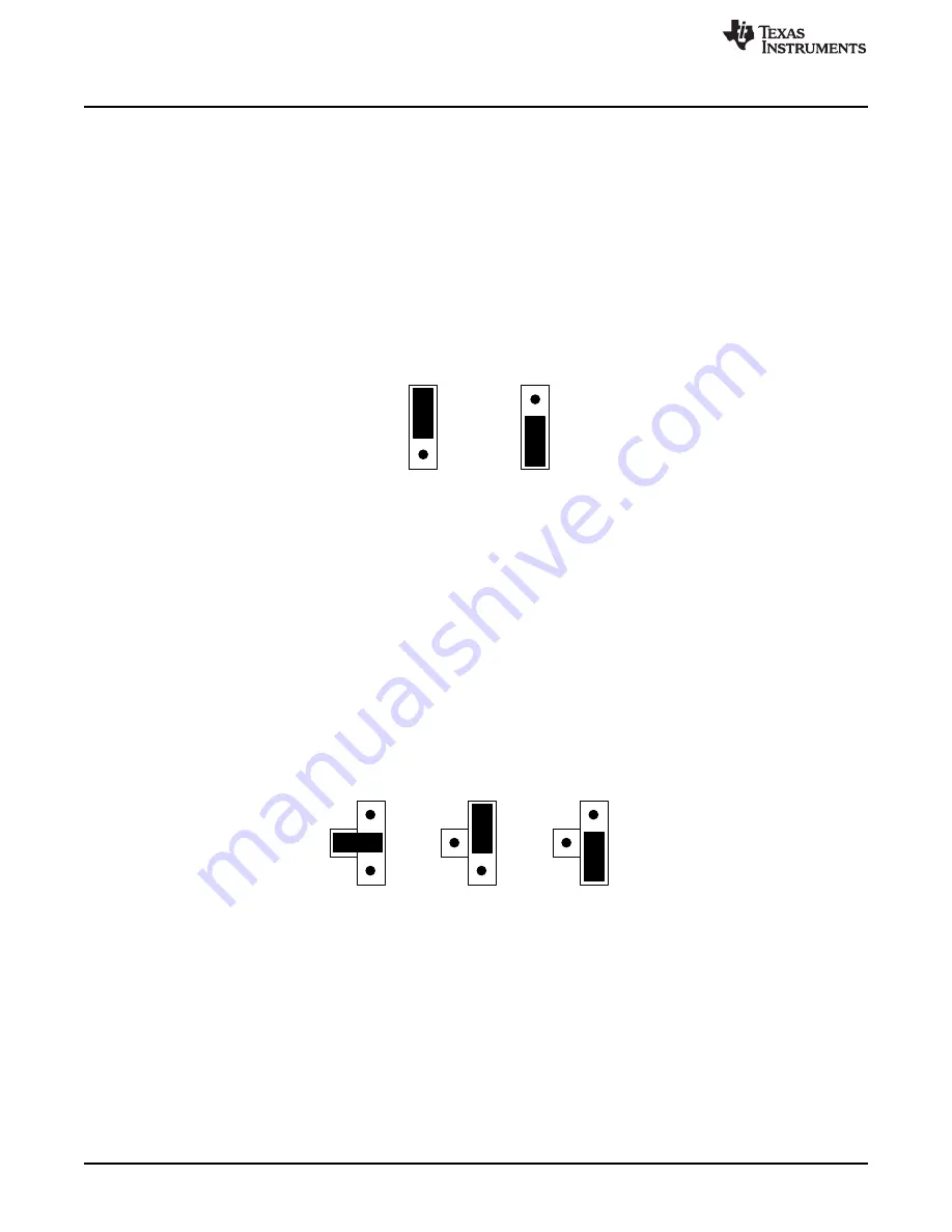
ASEL = VIN
ASEL = GND
1
2
3
4
1
2
3
4
1
2
3
4
V
U
S
B
V
IO
V
L
VUSB
Connection
V
U
S
B
V
IO
V
L
VL
Connection
Setup
6
SNVU509 – January 2016
Copyright © 2016, Texas Instruments Incorporated
LM36923HEVM User's Guide
2
Setup
This section describes the jumpers and connectors on the EVM as well as how to properly connect, set
up, and use the LM36923HEVM.
2.1
Input/Output Connector Description
VL / GND -
These are the power input terminals for the driver. The terminal block provides a power (VIN)
and ground (GND) connection to allow the user to attach the EVM to a cable harness.
VUSB VIO VL -
This pin provides power for the I
2
C and HWEN pullup resistors (RSCL, RSDA, RHWEN).
It is recommended that this pin is connected to the VIN pin. If desired, it can be connected to the
USB2ANY 3.3-V line provided by the USB interface connector. When VIO is connected to VIN
communication via the I
2
C interface may not be possible if the supply voltage to the LED driver is below
approximately 3 V.
Figure 2. VIO Jumper Settings
SDA SCL -
These connections allow the user to externally control the I
2
C lines. For independent control of
the I
2
C lines,
do not
connect the VIO jumper to either the 3.3 V or the VIN pin.
HWEN -
This is the jumper used to enable the LED driver (HWEN pin). The driver will be enabled when
the HWEN pin is high (VIO) and disabled when it is low (GND).
VL VIN -
The user can measure the Backlight Driver Input Current by omitting this jumper and inserting a
current meter between pins 1 (VIN) and 2 (VL).
ASEL -
This connector provides a method for controlling the ASEL input to configure the I
2
C slave
address. A jumper is required to operate the EVM. The LM36923HEVM GUI provides a method for setting
ASEL when a jumper is inserted between pins 2 and 4. When a jumper is inserted between pins 1 and 2
ASEL is connected to VIO through a 4.7-k
Ω
resistor (RA1). When a jumper is inserted between pins 2 and
3 ASEL is connected to GND through a 4.7-k
Ω
resistor (RA0).
Figure 3. ASEL Jumper Settings
PWM -
This pin provides a method for connecting either the USB2ANY or an external signal generator to
the PWM input. The PWM pin is connected to ground via a 4.7-k
Ω
resistor (RPWM). The LM36923HEVM
GUI provides a method for generating a PWM signal when a jumper is placed between connector pins 1
and 2. When connecting an external signal generator remove the jumper between pins 1 and 2 and
connect the signal generator to pin 1 and GND.
OUT -
This connector provides a way to disconnect the output voltage to each LED string and access to
the regulated output of the driver. The user can measure VOUT with reference to GND while connecting
and disconnecting the LED strings.