


www.ti.com
Selection Sidebar
5
SNLU159B – April 2014 – Revised September 2018
Submit Documentation Feedback
Copyright © 2014–2018, Texas Instruments Incorporated
DS125DF1610EVM
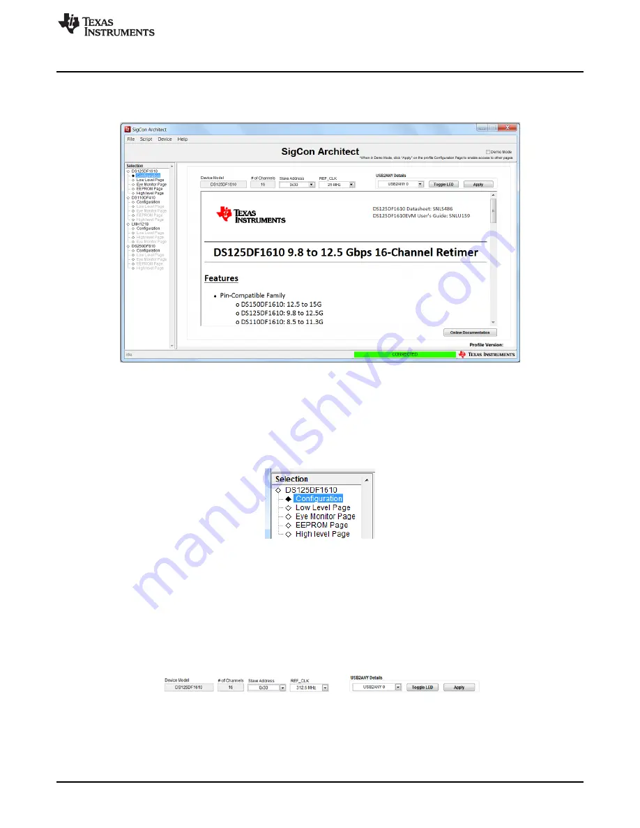
When starting SigCon architect, the graphic user interface should appear as in
Figure 2
with the
DS150DF1610 Retimer profile already loaded. In order to initiate reading and writing of the registers, the
‘Demo Mode’ box in the upper right hand corner must be deselected.
Figure 2. DS125DF1610 Profile GUI
4
Selection Sidebar
The ‘selection’ sidebar shows the current active device profiles. When the device is active and
configurable, this will show the sub-pages that are used to control the device: Configuration, Low Level
Page, Eye Monitor Page, EEPROM Page, and High Level Page.
Figure 3. Selection Sidebar
The content on each of these sub-pages will be detailed in each of the following sections.
5
Configuration Tab
The configuration tab’s main purpose is to specify the slave address for successful communication with
the DS125DF1610EVM. The default address is hex 0x30 as shown in
Figure 4
. If the ADDR0 (GPIO0) or
ADDR1 (GPIO1) jumper settings are altered, the SMBus address will need to be changed. Refer to the
datasheet for additional information.
Figure 4. Configuration Tab
After selecting the proper slave address, the board can be connected by clicking the apply button. If the
USB2ANY details drop down box does not show any values, then the board is not correctly connected to
your computer.