


JP1
VDD
DRV2604L
EN
IN/TRIG
GND
OUT+
OUT-
MSP430
PWM/
GPIO
P3.1
R8
EN
PWM
SDA
SCL
SDA
SCL
C11
AUDIO
R40, 0
Q
R41, NP
SDA SCL
R43, 0
Q
Hardware Configuration
www.ti.com
•
B2 – Select the on-board LRA
•
B3 – Trigger Select (1 = Internal Trigger, 2 = Ext. Edge, 3 = Ext. Level)
•
B4 – Trigger the waveform sequence using the MSP430.
4. Fill the waveform sequencer with waveforms using the external I
2
C port.
5. Choose either the on-board ERM or LRA using buttons B1 or B2.
6. Select either External Edge (2) or External Level (3) trigger using the B3 button. The trigger type
appears in binary on the mode LEDs.
7. Apply the external logic signal to the PWM test point to trigger the waveform.
4.6
External I
2
C Input
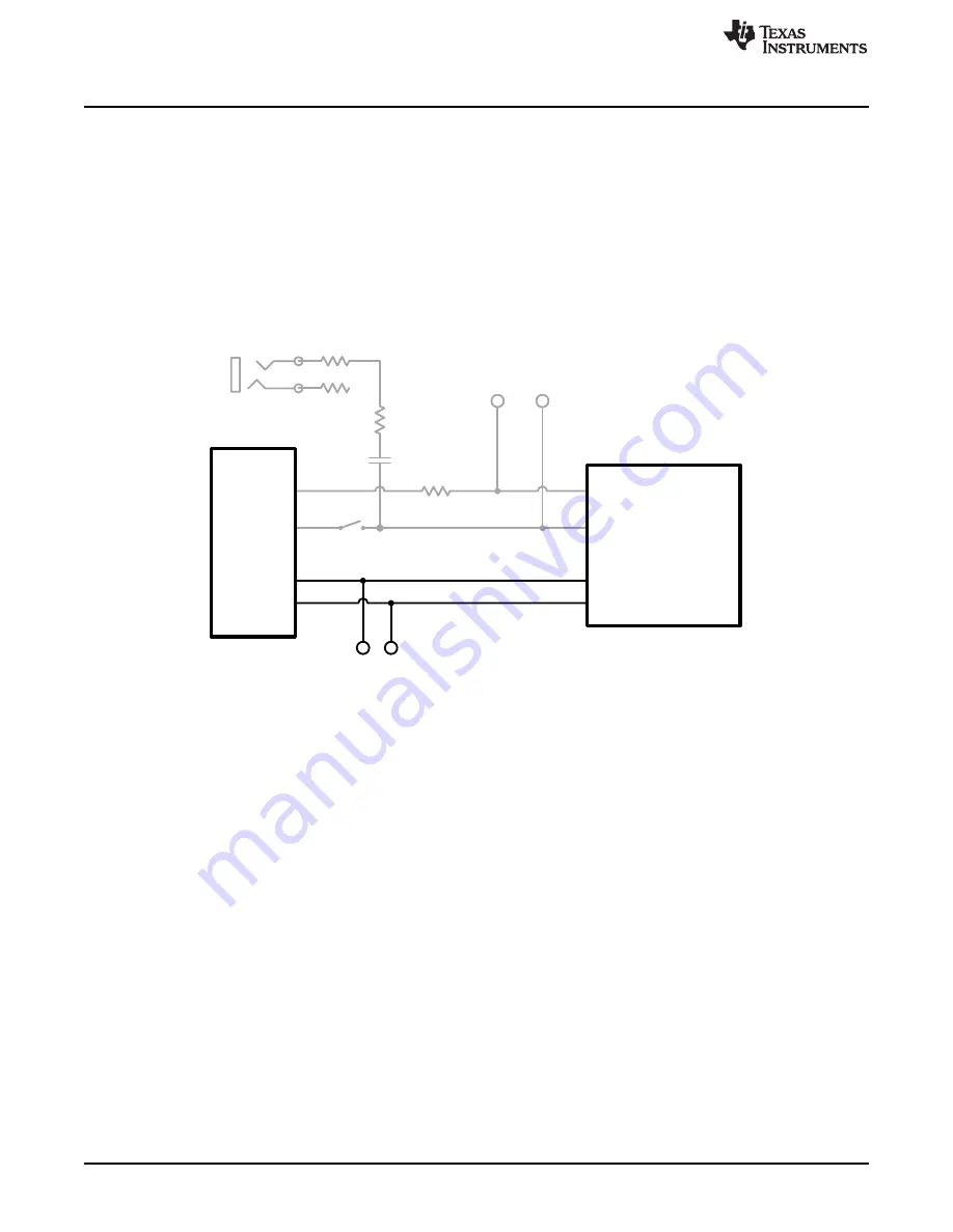
Figure 22. External I
2
C Input
The DV2604 can be controlled by an external I
2
C source. Attach the external controller to the I
2
C header
at the top of the board; be sure to connect SDA, SCL and GND from the external source.
I
2
C communication is possible only when the EN pin is set high. To enable the DRV2604L and allow
external I
2
C control, follow the instructions below.
1. Enter
Additional Hardware Modes
.
2. Select Mode 0 (00000’b) using the increment mode button (
+
).
•
B1 – Select the on-board ERM
•
B2 – Select the on-board LRA
•
B3 – Trigger Select (1 = Internal Trigger, 2 = Ext. Edge, 3 = Ext. Level)
•
B4 – Trigger the waveform sequence using the MSP430.
3. Choose either the on-board ERM or LRA using buttons B1 or B2. Either button sets the EN pin high
and turns on the
Active
LED.
4. Begin controlling the DRV2604L using the external I
2
C source.
18
DRV2604L ERM, LRA Haptic Driver Evaluation Kit
SLOU390A – May 2014 – Revised June 2014
Submit Documentation Feedback
Copyright © 2014, Texas Instruments Incorporated