background image

www.ti.com

Introduction to JESD204B Short Pattern Test

15

SLAA750 – July 2017

Submit Documentation Feedback

Copyright © 2017, Texas Instruments Incorporated

DAC38RF8x Test Modes

2.8

JESD204B Short Pattern Test Results

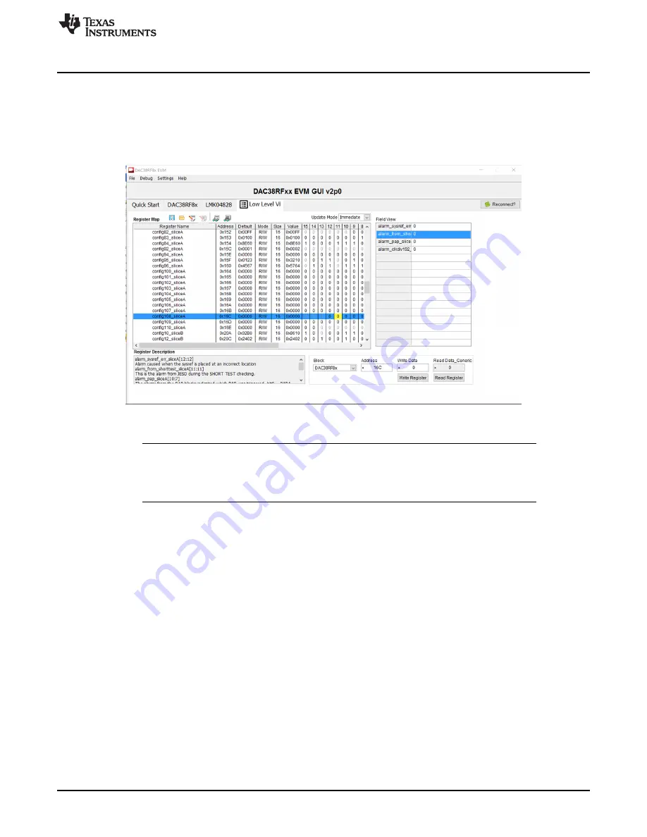
To read the alarm pin, scroll down and select register 0x16C. In the

Write Data

box, type the value 0000

and click the

Write Register

button. This write clears any alarms that may have been inadvertently

triggered in the setup process. Next click the

Read Register

button. If the value in the register remains a

zero, the test is passing and the configuration is correct. If the value changes to a 1, the alarm signal has
been detected and the user's setup could have issues.

Figure 19. DAC38RF8x EVM GUI Low Level View Tab Short Test Alarm Register

NOTE:

The register values in the GUI do not automatically update and can only be checked by

using the

Read Register

button. Also the short pattern test alarm must be cleared manually

between each reading using the write register tool. Disabling the short pattern test through
the short test enable register does not clear the alarm pin.

Содержание DAC38RF8x

Страница 1: ...SETUP for PRBS Tests 7 1 7 PRBS Test Results 9 2 Introduction to JESD204B Short Pattern Test 9 2 1 Required Hardware 9 2 2 Required Software 9 2 3 Hardware Setup 9 2 4 Configuring the DAC38RF8x 10 2 5 Register Writes for Custom Setup 11 2 6 TSW14J56 SETUP for JESD204B Short Pattern Test 11 2 7 Short Pattern Test Procedure 13 2 8 JESD204B Short Pattern Test Results 15 List of Figures 1 PRBS Hardwar...

Страница 2: ... PRBS Pseudo Random Binary Sequence Okawara 2013 The DAC38RF8x supports three different PRBS testing options PRBS7 PRBS23 and PRBS 31 In this test mode the PRBS pattern is supplied to the DAC input typically through an FPGA and the pattern is compared with the internally generated pattern of the DAC If the received pattern matches the generated pattern the test will pass and confirm good signal in...

Страница 3: ...6 Step 3 Connect a USB 3 0 Type A to Type B cable from the PC to TSW14J56 RevD USB 3 0 B port J9 Step 4 Connect a 5 V power supply to the DAC38RF8x EVM board using J21 Step 5 Connect a 5 V power supply to the TSW14J56 board using J11 Step 6 Turn on the TSW14J56 board by moving switch 6 to the ON position Step 7 Connect the signal generator output to LMKCLKIN J4 of the DAC38RF8x EVM board Configure...

Страница 4: ... section set The of DACs field to Dual DAC The of IQ pairs per DAC to 1 IQ pair The of SerDes lanes per DAC field to 4 lanes The Desired Interpolation field to 12x Step 4 In the On Chip PLL section check the PLL Enable box Set the M field to 6 the N field to 1 and the multiplier to 368 64 The DAC Clock Frequency box should automatically change to 8847 36 MHz Click the CONFIGURE DAC button After th...

Страница 5: ...Pin drop down menu Select the ALARM Pin Polarity field to be either Active High or Active Low Active high causes the alarm pin voltage to be set high if a PRBS error occurs Figure 4 DAC38RF8x EVM GUI Alarm Monitoring Tab Step 7 Select the SERDES and Lane Configuration sub tab see Figure 5 In the Align drop down menu select Disabled Next in the SERDES Test Pattern drop down menu select the desired ...

Страница 6: ...igure 6 DAC38RF8x EVM GUI JESD Block Tab 1 5 PRBS Register Writes for Custom Setup If the user is implementing the test without using the TI EVMs or GUI software the following register writes must be made in place of the previous steps to achieve the correct test setup The registers in the DAC are arranged according to page number and addresses The page number indicates to which portion of the DAC...

Страница 7: ...ter performing the register writes send the pattern to the DAC though the FPGA connection 1 6 TSW14J56 SETUP for PRBS Tests When the DAC has been configured properly the PRBS pattern is ready to be sent Launch the HSDC Pro application and navigate to the Quick Start tab A window pops up asking the user to select a device Select the TSW14J56 RevD board and click the OK button see Figure 7 Figure 7 ...

Страница 8: ...RBS Testing ini File Selection When the firmware is correct the PRBS pattern is ready to be loaded Under the Instrument Options menu select SERDES Test Options In the window that pops up select the transmitter tab at the top The DAC38RF8x EVM supports PRBS7 PRBS23 and PRBS31 Select the desired PRBS test and click the Apply button Figure 10 SERDES Test Options Menu ...

Страница 9: ...and GUIs To perform this test on a different board or without the TI GUI software configure the DAC into the desired state making sure to include the register writes in Section 2 5 2 1 Required Hardware This test procedure requires the following pieces of lab equipment DAC38RFxxEVM REV E board TSW14J56 REV D board 5 V DC power supplies Signal generator 2 2 Required Software This test procedure req...

Страница 10: ...p 1 Launch the DAC38RF8x GUI and select the Quick Start tab In the Quick Start tab toggle the DAC RESETB pin and click the LOAD DEFAULT button Step 2 After the default registers have been loaded configure the DAC to the desired operating mode The following figures show the setup for the 4421 configuration but the steps will be the same for all configurations Figure 11 DAC38RF8x GUI 4421 External C...

Страница 11: ...20 15 0 0x2B67 Update NCO frequency AB 5 1 0x121 15 0 0x0000 Update NCO frequency CD 6 1 0x122 15 0 0x0000 Update NCO frequency CD 7 1 0x123 15 0 0x0000 Update NCO frequency CD 8 1 0x1C 15 0 0x0000 Update NCO phase offset AB 9 1 0x1D 15 0 0x0000 Update NCO phase offset CD 10 1 0x28 1 1 SIF Sync 11 1 0x28 1 0 SIF Sync 12 2 0x28 1 1 SIF Sync 13 2 0x28 1 0 SIF Sync 2 6 TSW14J56 SETUP for JESD204B Sho...

Страница 12: ... by clicking the green arrow beside the Select DAC box Select the ini file corresponding to the configuration of the DAC Click Yes in the window that pops up to update the firmware Figure 15 HSDC Pro Select ini File Menu Step 6 Change the data rate at the top of the HSDC pro application to the appropriate data rate for the previously selected configuration The data rate is determined by taking the...

Страница 13: ...le 3 The given patterns are in 2 s complement hexadecimal format Table 3 JESD204B Short Test Patterns Pattern I0 Q0 I1 Q1 82121 7CB8 F431 6DA9 E520 42111 7CB8 F431 22210 7CB8 F431 12410 7CB8 F431 44210 7CB8 F431 6DA9 E520 24410 7CB8 F431 6DA9 E520 41121 7CB8 F431 81180 7C00 B800 F400 3100 6D00 A900 E500 2000 24310 7CB0 F431 6DA0 E520 41380 7CB0 F430 6DA0 E520 F870 E960 DA50 CB40 The generated file...

Страница 14: ... click the Load External Pattern File button and load in the pattern file Click the Send button The next step is to enable the short pattern test in the DAC In the DAC38RF8x GUI select the Low Level View tab Scroll down in the list of registers to the DAC38RF8x section and then select register 0x10C Write a 1 to bit 12 of this register to enable the short pattern test Figure 18 DAC38RF8x EVM GUI L...

Страница 15: ...ss Next click the Read Register button If the value in the register remains a zero the test is passing and the configuration is correct If the value changes to a 1 the alarm signal has been detected and the user s setup could have issues Figure 19 DAC38RF8x EVM GUI Low Level View Tab Short Test Alarm Register NOTE The register values in the GUI do not automatically update and can only be checked b...

Страница 16: ... TI Resource NO OTHER LICENSE EXPRESS OR IMPLIED BY ESTOPPEL OR OTHERWISE TO ANY OTHER TI INTELLECTUAL PROPERTY RIGHT AND NO LICENSE TO ANY TECHNOLOGY OR INTELLECTUAL PROPERTY RIGHT OF TI OR ANY THIRD PARTY IS GRANTED HEREIN including but not limited to any patent right copyright mask work right or other intellectual property right relating to any combination machine or process in which TI product...

Отзывы: