


C5535 DSPShield H/W Reference Manual
Version 0.1
In Collaboration with Stanford University
page
28
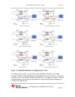
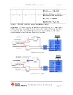
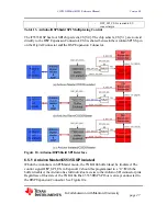
6.5.2 Arduino Slave/C5535 DSP Master
This is a possible communication link between the Arduino and the C5535 DSP. In this
configuration, DSP_SPI_EN should be programmed to a “1” and SPI_RX_SEL should be
set to a “0”. The former turns on the TXB0104 buffer and the latter routes the Arduino
MISO pin on the connector to the C5535 DSP’s SPI RX input. The C5535 DSP’s SPI
Chip Select 0 (CS0) signal is routed to the Arduino SS chip select pin. See Figure 10b.
6.5.3 Arduino Isolated/C5535 DSP Master
This configuration allows the C5535 DSP to be the sole Master of the Arduino SPI
interface. DSP_SPI_EN should be programmed with a “1” and SPI_RX_SEL should be
programmed with a “0”. The Arudino uC SPI pins should be tri-stated either by keeping
the Arduino in reset or programming its SPI pins as inputs. See Figure 10c.
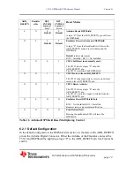
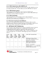
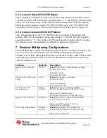
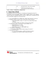
7 Resistor Multiplexing Configurations
The DSPShield has a number of multiplexing options that are controlled by resistors. The
previous sections have described some of the default configurations and possible
alternatives as well as control signals that can override them. Table 14 lists all the resistor
combinations and their functions. The defaults describe the configuration on power up
and after a manual reset.
Function
Resistors
Description
Input to C5535 USB_MXI
pin
R1, R53
Default:
USB_MXI = 12MHz External Oscillator
R1=DNI, R53=0 Ohm
USB_MXI = GND
R1=0 Ohm , R53=DNI
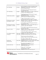
Ground 32.738 KHz Crystal
Casing
R5, R7
Default:
Crystal Case not grounded.
R5=DNI, R7=DNI
Crystal Case grounded.
R5=0 Ohm, R7=0 Ohm
C5535 System Clock
Generator Source
R8, R9,
R10, R59
Default:
Source from CLKIN pin (12MHz)
R8=DNI, R9=10K Ohm, R10=DNI, R59=0 Ohm
Source from 32.768KHz Crystal
R8=0 Ohm, R9=DNI, R10=0 Ohm, R59=DNI
Input to C5535 SPI RX pin
R18, R166
Default:
Source from Arduino Connector MISO
R18=10K Ohm, R166=DNI
Source from DSP_Expansion Connector
R18=DNI, R166=10K Ohm
C5535 Core Voltage Source
R25, R26,
R27, R28
Default:
Source from C5535 internal LDO.
R25=DNI, R26=0 Ohm, R27=0 Ohm, R28=DNI
Source from external LDO.
Содержание C5535 DSPShield
Страница 37: ...C5535 DSPShield H W Reference Manual Version 0 1 In Collaboration with Stanford University page 32...
Страница 38: ...C5535 DSPShield H W Reference Manual Version 0 1 In Collaboration with Stanford University page 33...
Страница 39: ...C5535 DSPShield H W Reference Manual Version 0 1 In Collaboration with Stanford University page 34...
Страница 40: ...C5535 DSPShield H W Reference Manual Version 0 1 In Collaboration with Stanford University page 35...
Страница 41: ...C5535 DSPShield H W Reference Manual Version 0 1 In Collaboration with Stanford University page 36...
Страница 42: ...C5535 DSPShield H W Reference Manual Version 0 1 In Collaboration with Stanford University page 37...
Страница 43: ...C5535 DSPShield H W Reference Manual Version 0 1 In Collaboration with Stanford University page 38...
Страница 44: ...C5535 DSPShield H W Reference Manual Version 0 1 In Collaboration with Stanford University page 39...
Страница 45: ...C5535 DSPShield H W Reference Manual Version 0 1 In Collaboration with Stanford University page 40...
Страница 46: ...C5535 DSPShield H W Reference Manual Version 0 1 In Collaboration with Stanford University page 41...
Страница 47: ...C5535 DSPShield H W Reference Manual Version 0 1 In Collaboration with Stanford University page 42...
Страница 48: ...C5535 DSPShield H W Reference Manual Version 0 1 In Collaboration with Stanford University page 43...
Страница 49: ...C5535 DSPShield H W Reference Manual Version 0 1 In Collaboration with Stanford University page 44...


