background image


C5535 DSPShield H/W Reference Manual 


Version 0.1 


In Collaboration with Stanford University 


page


iii


 Table of Contents 


1

C5535 DSPShield ...................................................................................................... 1

1.1

Key Features ...............................................................................................................1

1.2

DSPShield Architecture..............................................................................................2

1.3

User Control Elements ...............................................................................................3

1.4

DSPShield Application Photos ...................................................................................4

2

Power Management .................................................................................................. 4

2.1

External Power Interface ............................................................................................4

2.2

Internal Voltages ........................................................................................................6

2.3

Voltage Monitoring ....................................................................................................6

2.4

C5535 DSP Core Voltage ...........................................................................................7

3

C5535 DSP and Internal Peripherals ...................................................................... 7

3.1

Parallel and Serial Peripherals ....................................................................................7

3.2

Clock Sources .............................................................................................................8

3.3

ROM Bootloader ........................................................................................................9

3.4

/INT1, /INT0, XF, WAKEUP ..................................................................................10

3.5

USB Controller .........................................................................................................10

3.6

MMC/SDx Controller ...............................................................................................10

3.7

I2C ............................................................................................................................10

4

DSPShield Peripherals............................................................................................ 11

4.1

I2C GPIO Expander .................................................................................................11

4.2

OLED Display ..........................................................................................................14

4.3

TLV320ACI3204 Audio Codec ...............................................................................14

4.4

Micro SD Card Connector ........................................................................................14

4.5

DIP Switch Inputs, LEDs and Push Button Reset ....................................................14

4.6

DSP Expansion Connector .......................................................................................15

5

Emulation................................................................................................................. 16

5.1

FTDI FT2232H .........................................................................................................16

5.2

Power via XDS-USB ................................................................................................17

6

Arduino Interface .................................................................................................... 17

6.1

Arduino/DSPShield Interface Block Diagram .........................................................19

6.1.1

Interface Logic Levels ............................................................................... 19

6.1.2

Analog Inputs ............................................................................................ 20

6.2

Arduino/DSPShield Reset Multiplexing ..................................................................20

Содержание C5535 DSPShield

Страница 1: ...C5535 DSPShield H W Reference Manual Version 0 1 In Collaboration with Stanford University page i C5535 DSPSHIELD Hardware Reference Manual H W Rev A...

Страница 2: ...C5535 DSPShield H W Reference Manual Version 0 1 In Collaboration with Stanford University page ii Revision History Version Date Author Notes 0 1 Aug 12 2013 D Garcia 1 NOTES 1 Initial release 2...

Страница 3: ...7 3 1 Parallel and Serial Peripherals 7 3 2 Clock Sources 8 3 3 ROM Bootloader 9 3 4 INT1 INT0 XF WAKEUP 10 3 5 USB Controller 10 3 6 MMC SDx Controller 10 3 7 I2C 10 4 DSPShield Peripherals 11 4 1 I2...

Страница 4: ...lated C5535 DSP Master 28 7 Resistor Multiplexing Configurations 28 8 Stand Alone Mode 30 9 Assembly Drawings and Schematics 31 Reference documents Title source Owner Version 1 TMS320C5535 Data Sheet...

Страница 5: ...sor DNI Do Not Install Energia Open Source software IDE for TI Processors GPIO General Purpose Input Output I2C Inter Integrated Circuit 2 pin serial bus I2S Integrated Interchip Sound 4 pin serial bu...

Страница 6: ...ions Industrial Controls Fingerprint Biometrics Software defined Radio 1 1 Key Features The key features of the C5535 DSPShield are shown in Figure 1 The features include x TI TMS320C5535AZHHA10 100MH...

Страница 7: ...uted to its external pins The DSPShield maintains this flexibility by using additional discrete multiplexers to connect the C5535 s GPIO peripheral pins to the appropriate points on the board Additona...

Страница 8: ...H In Collabo d Block Dia ments ield through aders conne o the section own in the to witch for GPIN Button icro USB Conn ard Adapter ay Expansion Con ital Header 1 ital Header 2 wer Header alog Header...

Страница 9: ...hield Arduino UNO x DSPShield Arduino UNO Arduino Shield suggestions x DSPShield Arduino Leonardo using 2 USB cables x DSPShield DSP Daughter Card Audio Shield x DSPShield Arduino Shield DSP Daughter...

Страница 10: ...SHU IN SB SHU IN SB by SHU IN SB by SHU IN er Multiple e taken to pre settings may an invalid co ower Header the external W Reference M oration with S ent Block D P USB 5V JPA A OPEN nused SH I UNTED...

Страница 11: ...sourcing 13 DSP Expansion Header 3 3V 14 Emulator 3 3V 1 8V TP5 TP6 Internal AIC3204 LDO 1 AIC3204 AVDD TP5 2 AIC3204 DVDD TP6 1 3V TP10 LP3982 LDO VR2 1 C5535 CVDDRTC 2 C5535 CVDD 0 OHM resistor mux...

Страница 12: ...multipliers dual ALUs and a tightly coupled FFT hardware accelerator for performing math intensive signal processing algorithms It has a multiple I O peripherals that allow it to easily connect to se...

Страница 13: ...sion Connector IF R67 is Installed and R66 is Not Installed This is not the Default GPIO17 routed to the DSP Expansion Connector IF R69 is Installed and R68 is Not Installed This is not the Default Ta...

Страница 14: ...68 RTC R8 0 Ohm R9 DNI R10 0 Ohm R59 DNI Table 6 System Clock Generator Reference Source Select 3 3 ROM Bootloader The C5535 DSP has an on chip ROM Bootloader RBL It samples the following interfaces i...

Страница 15: ...e in can be mo ller allows th niversal Seria USB form fac oller bedded Mult onnected to a ault boot sou routed to th 1 GPIO 11 6 eripheral an interface emiconducto W Reference M oration with S P to th...

Страница 16: ...e C5535 DSP can enable the PCA9515B by setting DSP_I2C_EN on Port0 2 of GPIO Expander 2 to a 1 4 DSPShield Peripherals In addition to the C5535 DSP s internal peripherals the DSPShield has several ext...

Страница 17: ...ed to the original setting or when data is read from the port that generated the interrupt This interrupt feature of the GPIO Expander is very basic and lacks an interrupt mask capability NOTES 1 Ther...

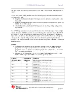
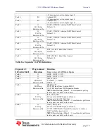
Страница 18: ...l Default 0 Table 8a Expander 1 GPIO Definitions Expander 2 I2CAddr 0x21 Programmed Direction Function Reset value all GPIO are Inputs Port0 0 O LED0 0 OFF 1 ON Port0 1 O LED1 0 OFF 1 ON Port0 2 O Pul...

Страница 19: ...mmed via the C5535 DSP s I2C bus and has an I2C address of 0x3C 4 3 TLV320ACI3204 Audio Codec The AIC3204 Audio Codec interfaces to the C5535 DSP via the I2C and I2S2 buses The C5535 DSP s I2S2 Bus is...

Страница 20: ...1 3 4 X_GPIO3V3_11 I O GPIO Expander2 Port1 1 5 X_GPIO3V3_12 I O GPIO Expander2 Port1 2 6 X_GPIO3V3_10 I O GPIO Expander2 Port1 0 7 X_SCL O I2C SCL 8 X_LCD_D9_I2S2_FS_GP19_SPI_CS0 I O C5535 PPMODE SIG...

Страница 21: ...Sig an embedde udio CCS t DS_USB mi not required try The print ulation capab nnecting it to mulator is th W Reference M oration with S I I I I CLK I I FS I I _RX I I _DX I I gnal Definit ed XDS100 V...

Страница 22: ...TR are tri stated and a resistor pulls up the EmuResetSrc signal Since RTS and DTR are defined as active low signals RTS and DTR will remain high after USB enumeration A PC can reset the DSPShield by...

Страница 23: ...ARD_ 5V I O 5V Can be Input or Output Source 3 ARD_SCK I O SPI_SCK 4 ARD_MOSI I O SPI MOSI 5 ARD_RESETN I O Bidirectional Reset Pin 6 GND Ground Table 10c Arduino ICSP Header P10 Pin Signal Name Dire...

Страница 24: ...k Diag Levels e with 5V a f the DSPSh JPD and JPE ce buffer IC W Reference M oration with S I Ana NO I O R94 R94 I O R93 R93 face Bloc Diagram is nterface a SP rface consist and IOREF gram and 3 3V v...

Страница 25: ...resistors in the input path to limit the input current They can be replaced with a different value for specific applications Additionally there are Schottky diodes for clamping the voltage swing to 1...

Страница 26: ...SPShield H In Collabo eld Reset Mu controlled b multiplexing the GPIOs o l pull down r W Reference M oration with S ultiplexing by the signal g configuratio f Expander 2 resistors wil Manual Stanford...

Страница 27: ...35 resets itself and DSPShield X X 1 0 C5535 Isolated from ARD_RESETN The C5535 cannot generate or receive an external reset on the ARD_RESETN pin X X 1 1 C5535 Resets Arduino The C5535 drives a logic...

Страница 28: ...DSPshield without resetting the Arduino In this case by switching R119 and R122 the EmuResetSrc signal is isolated from the ARD_RESETN pin See Figure 8f 6 3 DSPShield UART Multiplexing The C5535 DSP s...

Страница 29: ...th S 1 al Multiplex multiplexing er some con onnector pin efer to the sc Manual Stanford Un ARD_IO0 XDS SerPo ARD_IO1 XDS Seria ARD_IO 1 XDS SerPo XDS SerPo xing Contro modes base ntrol signal c ns du...

Страница 30: ...5 DS osing the Ar 535 DSP s R TXD line Se Port the C5535 The XDS JTA en UART_C duino s IO 1 should be ta W Reference M oration with S ing Modes r put of the 4 s UART sig 5535 DSP U DE value in th _MUX...

Страница 31: ...e PCA9515B is enabled ARD_I2C_EN 1 the C5535 DSP can operate as a master and communicate with the peripherals on board the DSPShield as well as any slaves on the Arduino side Conversely an Arduino can...

Страница 32: ...or d the DSP Ex ield SPI Int C5535 DSP Master mode in Expander has full indi TXB0104 t or See Figur W Reference M oration with S ltiplexing C s CS 3 0 T r CS0 is sha xpansion Con terface P Isolated e...

Страница 33: ...The DSPShield has a number of multiplexing options that are controlled by resistors The previous sections have described some of the default configurations and possible alternatives as well as control...

Страница 34: ...nsion Connector pin26 GPIO17 or 12MHz R68 R69 Default 12MHz Oscillator routed to DSP Expansion Connecter R68 0 Ohm R69 DNI C5535 GPIO17 routed to DSP Expansion Connector R68 DNI R69 0 Ohm Arduino SCL...

Страница 35: ...mode the recommended configuration is described below x Power the DSPShield via the DSP USB or XDS UXB shunt JPF connectors x Determine whether to source power to the Arduino Power Connector o Shunt...

Страница 36: ...C5535 DSPShield H W Reference Manual Version 0 1 In Collaboration with Stanford University page 31 9 Assembly Drawings and Schematics...

Страница 37: ...C5535 DSPShield H W Reference Manual Version 0 1 In Collaboration with Stanford University page 32...

Страница 38: ...C5535 DSPShield H W Reference Manual Version 0 1 In Collaboration with Stanford University page 33...

Страница 39: ...C5535 DSPShield H W Reference Manual Version 0 1 In Collaboration with Stanford University page 34...

Страница 40: ...C5535 DSPShield H W Reference Manual Version 0 1 In Collaboration with Stanford University page 35...

Страница 41: ...C5535 DSPShield H W Reference Manual Version 0 1 In Collaboration with Stanford University page 36...

Страница 42: ...C5535 DSPShield H W Reference Manual Version 0 1 In Collaboration with Stanford University page 37...

Страница 43: ...C5535 DSPShield H W Reference Manual Version 0 1 In Collaboration with Stanford University page 38...

Страница 44: ...C5535 DSPShield H W Reference Manual Version 0 1 In Collaboration with Stanford University page 39...

Страница 45: ...C5535 DSPShield H W Reference Manual Version 0 1 In Collaboration with Stanford University page 40...

Страница 46: ...C5535 DSPShield H W Reference Manual Version 0 1 In Collaboration with Stanford University page 41...

Страница 47: ...C5535 DSPShield H W Reference Manual Version 0 1 In Collaboration with Stanford University page 42...

Страница 48: ...C5535 DSPShield H W Reference Manual Version 0 1 In Collaboration with Stanford University page 43...

Страница 49: ...C5535 DSPShield H W Reference Manual Version 0 1 In Collaboration with Stanford University page 44...

Отзывы: