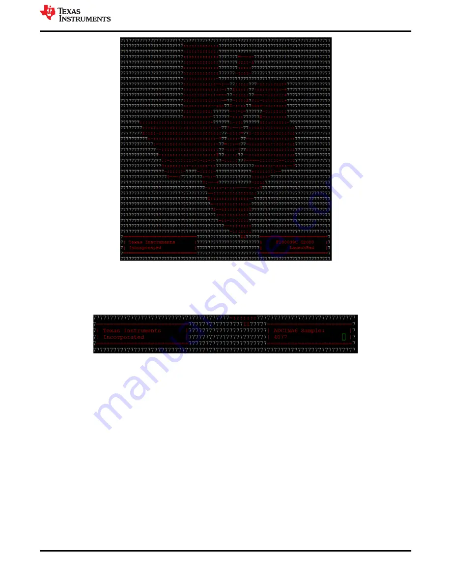
Figure 2-2. LaunchPad Demo Serial Terminal - TI Logo
After a few moments, the ADC value sampled on the ADCINA6 pin will appear in the bottom right corner of the
terminal and be updated each second. Using a jumper wire connect the ADCINA6 header to a 3.3V, GND, or
other 0-3.3V signal to see the on-screen value change.
Figure 2-3. LaunchPad Demo Serial Terminal - ADC Sampling
2.3 Programming and Running Other Software on the F28003x LaunchPad
The software packages described in
include example projects that can be loaded
and run on the F28003x LaunchPad. If you installed the
software to the default
installation path of
C:\ti\c2000\C2000Ware_<version>
, you can find driverLib based example applications in
C:\ti\c2000\C2000Ware_<version>\examples\F28003x
. The on-board XDS110 is used with the On-Chip Flash
Programmer tool to program applications to the F28003x LaunchPad.
Follow these steps to program example applications onto the F28003x LaunchPad development kit using the
on-board XDS110 debug probe:
1. Install
on a PC running Microsoft Windows.
2. Connect the USB-A cable plug in to an available USB port on the PC and plug the USB Type-C™ plug to the
port (USB101) on the F28003x LaunchPad.
3. Verify the following LEDs are illuminated:
a. LED7, at the top left of the board, indicating 5 V USB power.
b. LED0 indicating 3.3 V power to the XDS110 debug probe.
c. LED1 indicating 3.3 V power to the F280039C MCU.
4. Install Windows XDS110 and Virtual COM Port drivers if prompted. Installation instructions can be found at
.
Software Development
SPRUJ31 – APRIL 2022
C2000
™
F28003x Series LaunchPad
™
Development Kit
7
Copyright © 2022 Texas Instruments Incorporated


