Texas Instruments C2000 F28003x Series Скачать руководство пользователя страница 6

2.2 F28003x LaunchPad Demo Program

The LAUNCHXL-F280039C includes a TMSF280039CSPZ device pre-programmed with a demo program. When 
the LaunchPad is powered on the demo program begins with an LED blink sequence on LED4 and LED5. After 
a few seconds the device switches into an ADC sampling mode.

Every 1 second the ADC samples pin ADCINA6 and the sampled value is represented as follows: If the sample 
is above mid-scale (2048), the red LED4 will illuminate. If the sample is below mid-scale, the green LED5 will 
illuminate.

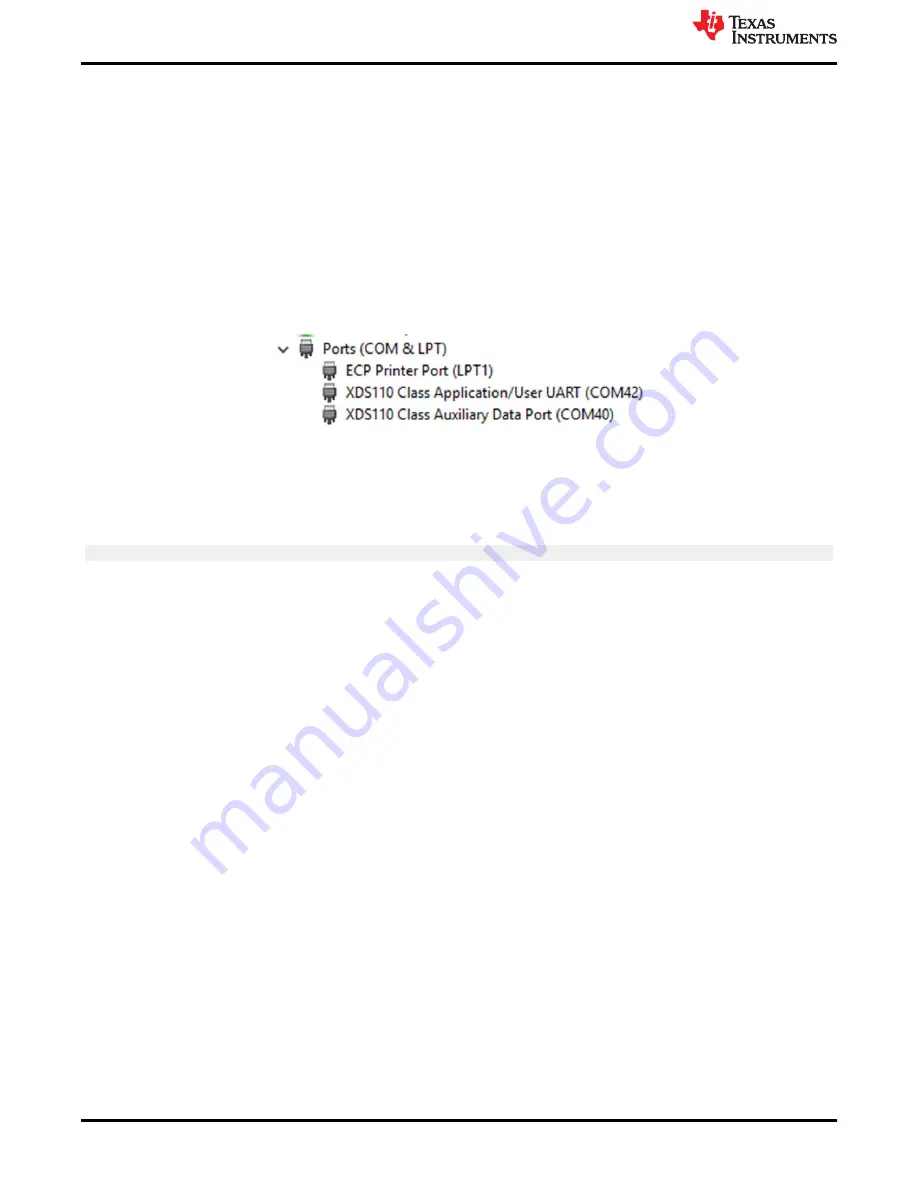
In addition to the LED indicators, ADC sample results are also displayed on your PC through the USB/UART 
connection. To view the UART information on your PC, first determine the COM port associated with the 
LaunchPad. To do this in Windows open the 

Device Manager

. Look for an entry under Ports (COM and LPT) 

titled "XDS110 Class Application/User UART (COM

X

)", where 

X

 is a number. Remember this number for when 

you open a serial terminal.

Figure 2-1. LaunchPad XDS110 COM Port

The demo application's UART data was tested using 

PuTTY

, which is a free and open-source terminal emulator

To view the UART data in a serial terminal program open the COM port found using the Windows 

Device 

Manager

 with the following settings.

115200 Baud, 8 data bits, no parity, 1 stop bit.

After properly opening the serial port in your serial terminal, reset the LaunchPad by pressing the S1 reset button 
and observe the serial terminal to see the TI logo in ASCII art.

Software Development

www.ti.com

6

C2000

 F28003x Series LaunchPad

 Development Kit

SPRUJ31 – APRIL 2022

Submit Document Feedback

Copyright © 2022 Texas Instruments Incorporated

Содержание C2000 F28003x Series

Страница 1: ...memory The LaunchPad also features two independent BoosterPack XL expansion connectors 80 pins on board Controller Area Network CAN transceiver supporting both standard CAN DCAN and CAN FD MCAN two 5...

Страница 2: ...Figure 3 1 F28003x LaunchPad Development Kit Block Diagram 9 Figure 3 2 LaunchPad Power Distribution Diagram 10 Figure 3 3 LaunchPad Power Plane Diagram 11 Figure 4 1 Top Signal Layer 1 17 Figure 4 2...

Страница 3: ...maximize expansion through the BoosterPack ecosystem 1 3 Specifications Table 1 1 summarizes the F28003x LaunchPad specifications Table 1 1 LAUNCHXL F280039C Specifications Parameter Value Board Supp...

Страница 4: ...rve as a starting point for such projects 5 Get Trained Review and download hours of written and video training materials on C2000 Real time Microcontrollers and related LaunchPads a See Getting Start...

Страница 5: ...EVM are listed below Known issues No issues to report at this time of initial release Special notes and considerations to be aware of Nothing to report at this time of initial release 2 Software Deve...

Страница 6: ...d with the LaunchPad To do this in Windows open the Device Manager Look for an entry under Ports COM and LPT titled XDS110 Class Application User UART COMX where X is a number Remember this number for...

Страница 7: ...e on board XDS110 is used with the On Chip Flash Programmer tool to program applications to the F28003x LaunchPad Follow these steps to program example applications onto the F28003x LaunchPad developm...

Страница 8: ...efine NAME 8 Right click the project name and select Rebuild Project in CCS 9 Launch the LAUNCHXL F280039C Target Configuration file and connect to the F28003x device Ensure that the Target Configurat...

Страница 9: ...SB ESD Device Boot Mode switch GPIO 24 32 2x10 pin BP Header FSI 2x5 Header Reset Button CAN Header Crystal Oscillator LED Driver eQEP 3 3 V 5 V Level Shifters eQEP Headers 2x10 pin BP Header 2x10 pin...

Страница 10: ...is factory programmed with a quick start demo program The quick start program resides in the on chip Flash memory and executes each time power is applied unless the application has been replaced with...

Страница 11: ...0 Connects the 5 V power on the XDS110 side of the board 5V0_XDS110 to the 5 V power on the F280039C side of the board 5V0_MCU JP2 3V3 Connects the 3 3 V power on the XDS110 side of the board 3V3_XDS1...

Страница 12: ...4 through the on board CAN Transceiver Both standard CAN and CAN FD Mux options exist on these F28003x device pins Switch S4 is used to route GPIO4 and GPIO5 to either the CAN transceiver and connecto...

Страница 13: ...e reference For best performance some additional circuitry may be required 3 1 11 Other Headers and Jumpers The LaunchPad has multiple jumpers to select different power sources for the board This Laun...

Страница 14: ...Virtual COM Port When plugged into a USB host the XDS110 enumerates as both a debugger and a virtual COM port J101 allows the user to connect the SCI UART from the F280039C to the debug probe to be pa...

Страница 15: ...ransceiver If S4 is set to UP off the GPIOs are routed to the BoosterPack connectors default case 3 3 5 FSI Routing One set of GPIOs with available FSI functionality are directly connected to the FSI...

Страница 16: ...Digital to Analog Converter on a TMS320F280x Digital Signal Control By default the RC filter is not populated Instead a0 ohm resistor is populated and the capacitor is left un populated 4 Board Design...

Страница 17: ...Figure 4 1 Top Signal Layer 1 www ti com Board Design SPRUJ31 APRIL 2022 Submit Document Feedback C2000 F28003x Series LaunchPad Development Kit 17 Copyright 2022 Texas Instruments Incorporated...

Страница 18: ...Figure 4 2 GND Layer 2 Board Design www ti com 18 C2000 F28003x Series LaunchPad Development Kit SPRUJ31 APRIL 2022 Submit Document Feedback Copyright 2022 Texas Instruments Incorporated...

Страница 19: ...Figure 4 3 PWR Layer 3 www ti com Board Design SPRUJ31 APRIL 2022 Submit Document Feedback C2000 F28003x Series LaunchPad Development Kit 19 Copyright 2022 Texas Instruments Incorporated...

Страница 20: ...for the LAUNCHXL F280039C is included in the LAUNCHXL F280039C design files download Board Design www ti com 20 C2000 F28003x Series LaunchPad Development Kit SPRUJ31 APRIL 2022 Submit Document Feedba...

Страница 21: ...the location of selected features of the board as well as the component locations Figure 4 5 F28003x LaunchPad Dimensions and Component Locations www ti com Board Design SPRUJ31 APRIL 2022 Submit Doc...

Страница 22: ...the board Ensure that 3 3 V is supplied to any of the available connectors on the target side of the isolation c Is the USB C cable connected to the PCB and is the USB region receiving power Is LED7...

Страница 23: ...e of two possible UART channels to be routed to the debug probe through J101 Ensure that S2 is configured to the appropriate UART channel for the application software For details see Section 3 3 2 6 R...

Страница 24: ...ain Output TPD4E004 4 Channel ESD Protection Array for High Speed Data Interfaces TPD4E05U06 4 Channel ESD Protection Array for for USB HDMI High Speed Interfaces TPS3702 High Accuracy Fixed Threshold...

Страница 25: ...ther than TI b the nonconformity resulted from User s design specifications or instructions for such EVMs or improper system design or c User has not paid on time Testing and other quality control tec...

Страница 26: ...These limits are designed to provide reasonable protection against harmful interference in a residential installation This equipment generates uses and can radiate radio frequency energy and if not in...

Страница 27: ...instructions set forth by Radio Law of Japan which includes but is not limited to the instructions below with respect to EVMs which for the avoidance of doubt are stated strictly for convenience and s...

Страница 28: ...any interfaces electronic and or mechanical between the EVM and any human body are designed with suitable isolation and means to safely limit accessible leakage currents to minimize the risk of electr...

Страница 29: ...R DAMAGES ARE CLAIMED THE EXISTENCE OF MORE THAN ONE CLAIM SHALL NOT ENLARGE OR EXTEND THIS LIMIT 9 Return Policy Except as otherwise provided TI does not offer any refunds returns or exchanges Furthe...

Страница 30: ...change without notice TI grants you permission to use these resources only for development of an application that uses the TI products described in the resource Other reproduction and display of thes...

Отзывы: