www.ti.com
Circuit Module Physical Construction
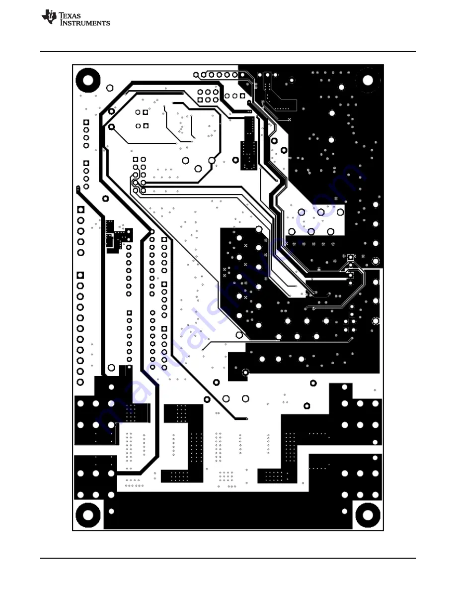
Figure 21. Layer 3
35
SLVU925B – April 2014 – Revised July 2014
bq76930 and bq76940 Evaluation Module User's Guide
Submit Documentation Feedback
Copyright © 2014, Texas Instruments Incorporated
Страница 1: ...bq76930 and bq76940 Evaluation Module User s Guide Literature Number SLVU925B April 2014 Revised July 2014...
Страница 2: ...bqStudio Operation 18 5 5 Firmware Programming 20 5 6 Data Memory Configuration 22 5 7 Chemistry View 23 5 8 Calibration 24 5 9 Device Control 26 6 bq769x0 Circuit Module Use 26 6 1 Cell Simulator 26...
Страница 3: ...Top Silk Screen 32 19 Top Layer 33 20 Layer 2 34 21 Layer 3 35 22 Bottom Layer 36 23 Bottom Silk Screen 37 24 bq76930EVM Top Assembly 38 25 bq76930EVM Bottom Assembly 39 26 bq76930EVM Schematic Diagr...
Страница 4: ...ication Summary 7 3 Reducing Cell Count 28 4 bq76930EVM Circuit Module Bill of Materials 40 5 bq76940EVM Circuit Module Bill of Materials 51 4 List of Tables SLVU925B April 2014 Revised July 2014 Subm...
Страница 5: ...s d All interface circuits power supplies evaluation modules instruments meters scopes and other related apparatus used in a development environment exceeding 50 VRMS 75 VDC must be electrically locat...
Страница 6: ...ted circuit module for 10 cell or 15 cell configuration for quick setup Power connections available on screw terminals Communication signals available on 4 pin connector Resistor cell simulator for qu...
Страница 7: ...gs and cautions are noted for the safety of anyone using or working close to the bq76920 EVM Observe all safety precautions Warning Warning Hot surface Contact may cause burns Do not touch Caution Do...
Страница 8: ...ecting the AFE to the gauge 4 If the EV2300 is used install shunts on the SCL and SDA pull up headers Remove any pull up shunts when using the EV2400 5 Close all dip switch positions default is closed...
Страница 9: ...mporary location on your computer 4 Install 4 shunts on the J14 header connecting the AFE to the gauge SCL SDA REGOUT and ALERT 5 Install shunts on the SCL and SDA pull up headers 6 Install shunts on...
Страница 10: ...ET_EN bit is now set and that the CHG and DSG FET status is shown enabled 22 Select the Calibration bq78350 view 23 Enter the board temperature in the Temperature Sensor boxes and click on the Calibra...
Страница 11: ...ort power_management battery_management m videos__files 458983 aspx or http www ti com tool ev2300 To install the drivers 1 Navigate to the installation directory typically C Program Files x86 Texas I...
Страница 12: ...The interface adapter should not be connected to the I2C connector if a gauge or MCU is connected to the bus Board pull up shunts must be installed for the EV2300 and removed for the EV2400 4 4 Softw...
Страница 13: ...to read the device CRC read from device does not match calculated CRC Check that the Read Device button was used to detect the device Check the connection of the 4 pin cable or its routing near high...
Страница 14: ...gisters View The Read Device button at the top of the Registers view provides important setup of the bq76940 bq76930 bq76920 software and the IC The software reads the factory gain and offset data fro...
Страница 15: ...en checked The update interval is displayed and can be changed with the Change Interval button The Logging section has the Start Logging button The values read from the device can be saved to a file S...
Страница 16: ...Sequence button on the left side of the window or from the menu A sequence can be run by selecting its Execute button The results of the sequence are shown in the Sequence Dialog section The sequence...
Страница 17: ...uired do not move them from the directory Typical uses of a sequence might include Reading clearing faults then enabling CHG and DSG outputs Setting ship mode Setting a balance pattern Any repetitive...
Страница 18: ...uct bq78350 or search from power ti com Check periodically for software updates Use the following steps to install the bqStudio software 1 Copy the archive file to a directory of your choice extract a...
Страница 19: ...dio popup window will indicate a free adapter is not available Acknowledge the message to proceed Errors will appear in the left bottom border of the Battery Management Studio screen Correct the probl...
Страница 20: ...owse button and select the file to be programmed Using the Execute after programming feature is recommended Click on the Program button to start programming A Progress Information window will display...
Страница 21: ...is the same as the version previously selected in the Target Selection Wizard no change may be apparent but restarting to allow tool configuration is still recommended Figure 10 Dashboard Adapter and...
Страница 22: ...that must typically be changed with the EVM The AFE Cell Map is a physical location of the cells Refer to the bq78350 TRM SLUUAN7 for information on this and other configuration parameters Data Memor...
Страница 23: ...ta Memory parameter but by using the Chemistry view Loading the chemistry is not required for simple operation of the EVM but will be desired for setup of the board or a part for operation with cells...
Страница 24: ...he calibration Values left blank or entered as 0 are not calibrated When successful a green check appears next to the button as shown in Figure 15 If there is an error a red X appears instead with a m...
Страница 25: ...Figure 14 Calibration View Figure 15 Example Voltage Calibration Successful 25 SLVU925B April 2014 Revised July 2014 bq76930 and bq76940 Evaluation Module User s Guide Submit Documentation Feedback C...
Страница 26: ...3 on the bq76940EVM Other components provide support for the IC and connections to the board Basic operation is described in the quick start guide For details of the circuit refer to the physical con...
Страница 27: ...If modified for low voltage operation do not operate the board at its normal upper voltage limit Operation of the board with voltages outside the operating range of the components on the board can dam...
Страница 28: ...provides a signal path to the used input For the best evaluation with reduced cells in a transient environment short the VCx pins at the capacitor or VCx test points and remove the unused cell s inpu...
Страница 29: ...e as cells are connected If desired the cell simulator switches can be closed during cell connection and opened after cell connection The switches must be opened after connection of cells or the cells...
Страница 30: ...uppression component D16 to D21 and D32 to D37 are patterns for Schottky diodes When the battery is short circuited the cell voltages will drop and the inputs are pulled below the group power referenc...
Страница 31: ...y connection with cell connections on the left side to a terminal block and high current screw terminals Control connections are on the left top Pack terminals are on the right side using screw termin...
Страница 32: ...al Construction www ti com Figure 18 Top Silk Screen 32 bq76930 and bq76940 Evaluation Module User s Guide SLVU925B April 2014 Revised July 2014 Submit Documentation Feedback Copyright 2014 Texas Inst...
Страница 33: ...Module Physical Construction Figure 19 Top Layer 33 SLVU925B April 2014 Revised July 2014 bq76930 and bq76940 Evaluation Module User s Guide Submit Documentation Feedback Copyright 2014 Texas Instrum...
Страница 34: ...ysical Construction www ti com Figure 20 Layer 2 34 bq76930 and bq76940 Evaluation Module User s Guide SLVU925B April 2014 Revised July 2014 Submit Documentation Feedback Copyright 2014 Texas Instrume...
Страница 35: ...t Module Physical Construction Figure 21 Layer 3 35 SLVU925B April 2014 Revised July 2014 bq76930 and bq76940 Evaluation Module User s Guide Submit Documentation Feedback Copyright 2014 Texas Instrume...
Страница 36: ...ical Construction www ti com Figure 22 Bottom Layer 36 bq76930 and bq76940 Evaluation Module User s Guide SLVU925B April 2014 Revised July 2014 Submit Documentation Feedback Copyright 2014 Texas Instr...
Страница 37: ...ule Physical Construction Figure 23 Bottom Silk Screen 37 SLVU925B April 2014 Revised July 2014 bq76930 and bq76940 Evaluation Module User s Guide Submit Documentation Feedback Copyright 2014 Texas In...
Страница 38: ...The bq7693000 is aligned with pin 1 of the U1 board pattern Components to support the upper cells are not installed Figure 24 and Figure 25 show the bq76930EVM assembly Figure 24 bq76930EVM Top Assemb...
Страница 39: ...Physical Construction Figure 25 bq76930EVM Bottom Assembly 39 SLVU925B April 2014 Revised July 2014 bq76930 and bq76940 Evaluation Module User s Guide Submit Documentation Feedback Copyright 2014 Texa...
Страница 40: ...SOD 323 MMSZ5232BS 7 F Diodes Inc D13 D14 D15 D25 D26 D43 D44 D53 D54 D48 D49 D50 D51 D52 5 Green LED Green SMD 1 6x0 8x0 8mm LTST C190GKT Lite On D55 1 Orange LED Orange SMD 1 6x0 8x0 8mm LTST C190K...
Страница 41: ...99KFKEA Vishay Dale R43 1 3 01k RES 3 01k ohm 1 0 125W 0805 0805 CRCW08053K01FKEA Vishay Dale R75 R78 R101 R103 R107 6 100k RES 100k ohm 1 0 125W 0805 0805 CRCW0805100KFKEA Vishay Dale R109 R77 R129 R...
Страница 42: ...G ON Semiconductor D38 D39 D40 D42 0 Diode TVS Uni 30V 600W SMB SMB SMBJ30A 13 F Diodes Inc HS1 HS2 HS3 HS4 0 Heatsink DDPAK TO 263 SMT Heatsink DDPAk 573300D00010G Aavid J9 0 Header 3 5mm 5POS R A TH...
Страница 43: ...4 mm Disc 5x8 4 mm 103AT 2 SEMITEC Corporation TP1 0 Black Test Point TH Multipurpose Black Keystone5011 5011 Keystone TP2 TP14 0 Red Test Point TH Multipurpose Red Keystone5010 5010 Keystone TP7 TP8...
Страница 44: ...S4 573300D00010G DNP 45V D1 SMCJ45A BATT BATT 1 J1 8199 1 J2 8199 1 J3 8199 1 J4 8199 100V Q5 ZXMP10A13FTA NT1 Net Tie GND CHG CHG DSG C0 BATT SRP SRN PFD PACK 0 66V or 0 44V 15A Input 0 66V or 0 44V...
Страница 45: ...6V D7 10 0k R33 1 F C10 100 R10 1 00k R22 5 6V D6 10 0k R32 TP26 DNP TP25 DNP TP24 DNP TP23 DNP TP22 DNP TP21 DNP 10 0k ohm t RT2 4700pF C25 10 0k ohm t RT3 DNP 4700pF C24 DNP 1 F C23 1 F C22 DNP 1 0...
Страница 46: ...F C34 D38 SMBJ30A 13 F DNP 10 F C35 D39 SMBJ30A 13 F DNP 1 00k R59 1 00k R57 DNP 100 R60 DNP BAT shunt 100 R61 VC10X shunt 100 R62 VC5X shunt GND GND TP49 100 R79 1 2 3 J10 DNP Test points 100k R74 DN...
Страница 47: ...5 6V D43 5 6V D54 5 6V D53 TP60 DNP TP56 DNP KEYIN PRES 1 2 3 4 5 6 7 8 9 10 J14 PEC05DAAN GND GG_PWR 0 R85 DNP Q21 DNP TP59 AFE GG 100V Q17 BSS123 Alternate pattern for low voltage low current opera...
Страница 48: ...F 49 9k R122 698 R121 0 R123 GND 100V Q22 BST82 215 1 2 3 4 5 6 13 14 15 16 7 12 8 9 10 11 S4 76SB08ST 1 2 3 4 5 6 13 14 15 16 17 18 7 12 8 9 10 11 S3 76SB09ST C14 BATT C15 C13 C12 C11 C10 C9 C8 C7 C6...
Страница 49: ...bq76940EVM uses all 15 cells provided on the board Figure 31 and Figure 32 show the bq76940EVM assembly Figure 31 bq76940EVM Top Assembly 49 SLVU925B April 2014 Revised July 2014 bq76930 and bq76940...
Страница 50: ...nstruction www ti com Figure 32 bq76940EVM Bottom Assembly 50 bq76930 and bq76940 Evaluation Module User s Guide SLVU925B April 2014 Revised July 2014 Submit Documentation Feedback Copyright 2014 Texa...
Страница 51: ...10 D11 D12 D13 D14 21 5 6V Diode Zener 5 6V 200mW SOD 323 SOD 323 MMSZ5232BS 7 F Diodes Inc D15 D25 D26 D27 D28 D29 D30 D31 D43 D44 D53 D54 D48 D49 D50 D51 D52 5 Green LED Green SMD 1 6x0 8x0 8mm LTST...
Страница 52: ...9 R30 R31 R57 R58 R59 R63 R64 R65 R66 R67 R68 R10 R11 R12 R13 R14 R15 R16 R17 15 100 RES 100 ohm 1 0 25W 1206 1206 CRCW1206100RFKEA Vishay Dale R18 R19 R52 R53 R54 R55 R56 R32 R33 R34 R35 R36 R37 R38...
Страница 53: ...OD 123 SOD 123 BAT54T1G ON Semiconductor D38 D39 D40 D42 0 Diode TVS Uni 30V 600W SMB SMB SMBJ30A 13 F Diodes Inc HS1 HS2 HS3 HS4 0 Heatsink DDPAK TO 263 SMT Heatsink DDPAk 573300D00010G Aavid J10 0 H...
Страница 54: ...t Module Physical Construction www ti com Table 5 bq76940EVM Circuit Module Bill of Materials continued Designator Qty Value Description Package Reference Part Number MFR Alt Part Number Alt MFR TP7 T...
Страница 55: ...9 10 0k R35 1 F C12 100 R12 1 00k R24 5 6V D8 10 0k R34 1 F C11 100 R11 1 00k R23 5 6V D7 10 0k R33 1 F C10 100 R10 1 00k R22 5 6V D6 10 0k R32 TP26 DNP TP25 DNP TP24 DNP TP23 DNP TP22 DNP TP21 DNP 10...
Страница 56: ...30A 13 F DNP 1 00k R59 1 00k R57 100 R60 BAT shunt 100 R61 VC10X shunt 100 R62 VC5X shunt GND GND TP49 100 R79 1 2 3 J10 DNP Test points 100k R74 DNP 100k R75 1 F C37 D42 SMBJ30A 13 F DNP GND TP39 TP3...
Страница 57: ...5 6V D43 5 6V D54 5 6V D53 TP60 DNP TP56 DNP KEYIN PRES 1 2 3 4 5 6 7 8 9 10 J14 PEC05DAAN GND GG_PWR 0 R85 Q21 DNP TP59 AFE GG 100V Q17 BSS123 Alternate pattern for low voltage low current operation...
Страница 58: ...698 R121 0 R123 DNP GND 100V Q22 BST82 215 1 2 3 4 5 6 13 14 15 16 7 12 8 9 10 11 S4 76SB08ST 1 2 3 4 5 6 13 14 15 16 17 18 7 12 8 9 10 11 S3 76SB09ST C14 BATT C15 C13 C12 C11 C10 C9 C8 C7 C6 C5 C4 C...
Страница 59: ...nged Li Ion and Li Polymer to Li Ion and Phosphate in the first Features bullet 6 Changed 5 cell parallel FET to 10 or 15 cell in first sentence of the bq769x0 Circuit Module Performance Specification...
Страница 60: ...sponsible for compliance with all legal regulatory and safety related requirements concerning its products and any use of TI components in its applications notwithstanding any applications related inf...
Страница 61: ...Mouser Electronics Authorized Distributor Click to View Pricing Inventory Delivery Lifecycle Information Texas Instruments BQ76930EVM BQ76940EVM...