Introduction to C5545 BoosterPack Board
www.ti.com
26
SPRUI90 – September 2016
Submit Documentation Feedback
Copyright © 2016, Texas Instruments Incorporated
TMS320C5545 BoosterPack Hardware
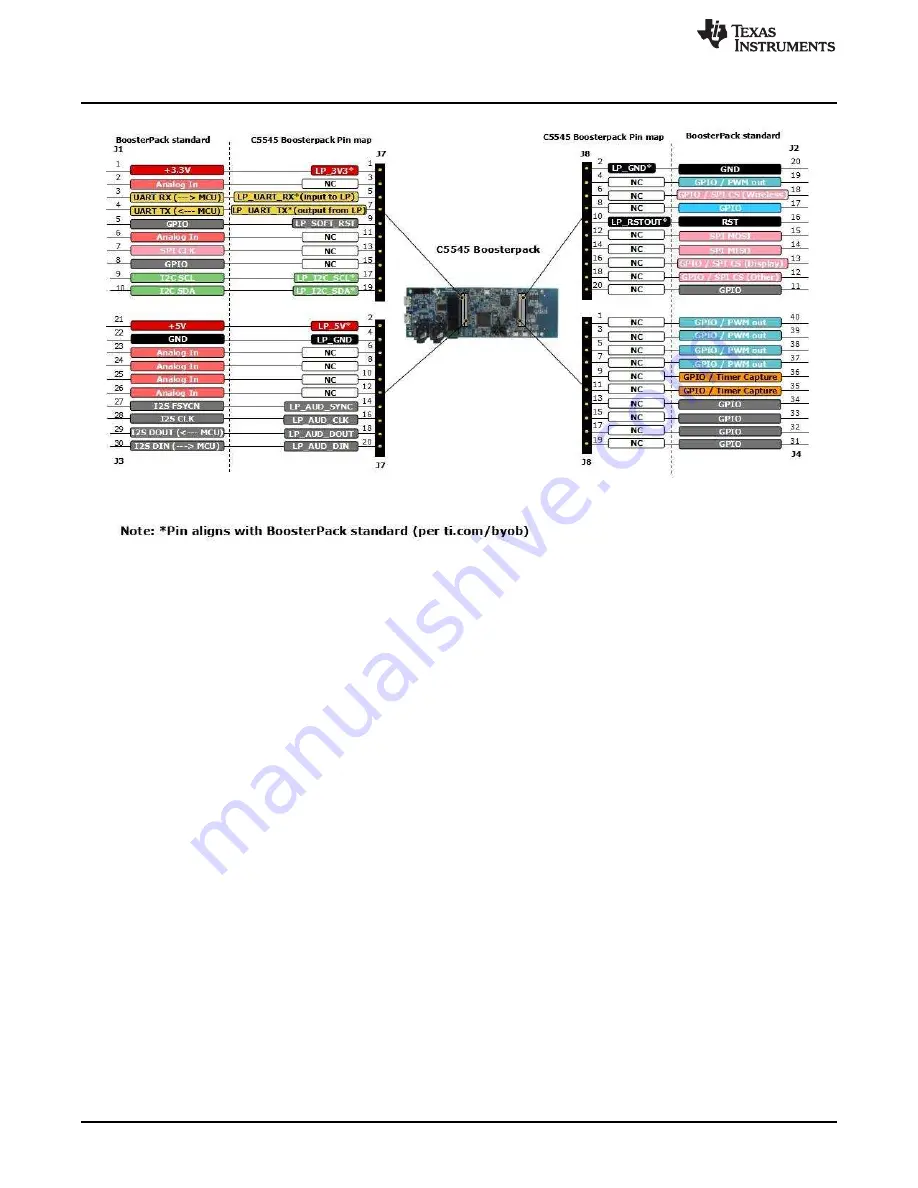
Figure 24. C5545 BoosterPack Pin Map
Страница 1: ...TMS320C5545 BoosterPack Hardware User s Guide Literature Number SPRUI90 September 2016...
Страница 2: ...ace 15 2 5 LED and Switch Interface 16 2 6 CC2650 SPI and GPIO Interface 17 2 7 Micro SD CARD Interface 18 2 8 OLED Display Interface 18 2 9 Audio CODEC Interface 19 2 10 USB Interface 20 2 11 UART In...
Страница 3: ...ace 20 15 UART Interface Schematics 20 16 FT2232 and C5545 default 20 17 LaunchPad and CC2650 20 18 FT2232 and CC2650 21 19 LaunchPad and C5545 21 20 Connection Between C5545 and LaunchPad 22 21 Level...
Страница 4: ...3 GPIO Mapping 28 4 C5545 BoosterPack Board Connectors 31 5 JTAG XDS100 Micro USB Connector FT2232H 32 6 JTAG Header CC2650 33 7 Audio Line In 3 5 mm Stereo Jack 33 8 Audio Headphone Out 3 5 mm Jack 3...
Страница 5: ...rPack is a high performance low power platform that enables users to evaluate and develop for the TMS320C5545A processor and its peripherals The BoosterPack interfaces to LaunchPad boards such as MSP4...
Страница 6: ...e USB port with integrated 2 0 high speed PHY supports both high and full speed device Software compatible with C55x devices Three integrated LDOs On chip ROM bootloader 118 terminal 7x7 mm 0 5mm pitc...
Страница 7: ...d an included out of box audio demo application with source code to accelerate your time to market The out of box demo package includes an audio playback demo running on the C5545 BoosterPack and a co...
Страница 8: ...lizer application on the Android device 6 Allow the application to enable Bluetooth if not already enabled 7 Press the scan button to start scanning for the C5545 BoosterPack 8 Press the connect butto...
Страница 9: ...Ds LD1 2 3 SWITCHES SW2 3 4 UART SELECTION JUMPERS JP3 JP2 LINE IN JACK J6 HEAD PHONE JACK J5 XDS100 POWER LED LD4 CLIENT USB CONN J1 DEBUG USB CONN J9 www ti com Overview 9 SPRUI90 September 2016 Sub...
Страница 10: ...lash U8 MX25R1635FM1ILO BOARD TO BOARD CONN for DXQFK3DG J7 MICRO SD CARD CONN J3 Overview www ti com 10 SPRUI90 September 2016 Submit Documentation Feedback Copyright 2016 Texas Instruments Incorpora...
Страница 11: ...r IC TPS62161DSGT and TPS62162DSGT U21 and U20 respectively takes care of the generation of various powers to the C5545 Processor listed below Core Voltage CVDD Internal LDO Voltages DSP_LDO ANA_LDO U...
Страница 12: ...e C5545 BoosterPack contains an on board XDS100 USB emulator based on the FTDI FT2232 dual port chip One of the FT2232 ports is configured for UART and the other for JTAG All the JTAG lines are connec...
Страница 13: ...other 12 MHz oscillator is connected to the XDS100 A 32 768 kHz is connected to the C5545 DSP for the RTC section The C5545 DSP clock source is selected by the clock select jumper J2 to choose between...
Страница 14: ...iated reset by LaunchPad s RESET button or debugger on pin 16 C5545 DSP can be reset independently by the XDS100 USB debugger CC2650 wireless MCU can be reset independently by the following Software i...
Страница 15: ...5FM1IL0 from Macronix which is interfaced to the C5545 DSP as shown in Figure 7 The SPI port of the DSP is shared with the SPI Flash and the CC2650 which is selected through chip select 0 and 2 respec...
Страница 16: ...ruments Incorporated TMS320C5545 BoosterPack Hardware 2 5 LED and Switch Interface Three push buttons and three green LEDs are provided for user input and status Figure 8 Switch and LED Connection For...
Страница 17: ...processor that runs at 48 MHz Communication between the CC2650 and the C5545 devices is through a SPI interface using CS2 In addition two GPIO signals are connected between the C5545 DSP and the CC265...
Страница 18: ...ontains ESD protection diodes and integrated pull ups for the data and command signals The card detect pin from the micro SD card connector is connected to the C5545 DSP GPIO29 to detect the presence...
Страница 19: ...capabilities fixed predefined and parameterizable signal processing blocks integrated PLL and flexible digital interfaces This audio CODEC is interfaced to the I2S2 port and I2C bus of the C5545 Audi...
Страница 20: ...t micro USB type B connector J1 as shown in Figure 13 ESD diodes are provided for the USB signals The USB ID pin on the connector is left floating as this is device only port Figure 13 USB Interface 2...
Страница 21: ...DGND DSP_UART_TX FT2232_BUFF_UART_RX CC2650_UART_T LP_BUFF_UART_RX FT2232_BUFF_UART_TX CC2650_UART_R DSP_UART_RX LP_BUFF_UART_TX LaunchPad CC2650 JP3 1 2 4 3 JP2 1 2 4 3 TP 6 DGND DSP_UART_TX FT2232_...
Страница 22: ...LaunchPad headers It can be connected to either the MSP432 LaunchPad Part Number MSP EXP432P401R or the CC3200 Launchpad LAUNCHXL Rev3 1 Level translators U12 U13 SN74AVC4T245 for UART and I2S interfa...
Страница 23: ...oltage between the LaunchPad 3 3 V and C5545 BoosterPack 1 8 V level shifters are present at the LaunchPad headers These level shifters require a VCC supply from the LaunchPad to operate When no Launc...
Страница 24: ...ut this also means that an attached LaunchPad cannot be powered by the BoosterPack Figure 22 C5545 BoosterPack Powering Options 2 12 3 LaunchPad Reset refer to Section 2 3 Hardware reset from the Laun...
Страница 25: ...320C5545 BoosterPack Hardware 2 12 4 Connecting C5545 BoosterPack to MSP432P401R LaunchPad Connect the C5545 BoosterPack to MSP432P401R LaunchPad as shown in Figure 20 Insert the C5545 BoosterPack hea...
Страница 26: ...n to C5545 BoosterPack Board www ti com 26 SPRUI90 September 2016 Submit Documentation Feedback Copyright 2016 Texas Instruments Incorporated TMS320C5545 BoosterPack Hardware Figure 24 C5545 BoosterPa...
Страница 27: ...ation for the C5545 to boot properly and for the Launchpad device ex MSP432 to access the bus Before booting from the SD card the C5545 boot loader polls the I2C bus looking for an I2C EEPROM with val...
Страница 28: ...GPIO mapping for C5545 BoosterPack Board is provided in Table 3 Table 3 GPIO Mapping GPIO Name C5545 DSP Pin Purpose Internal External Pull Up PU Pull Down PD0 CC2650_PWRMGT1 GP 10 POWER MANAGEMENT IN...
Страница 29: ...eedback Copyright 2016 Texas Instruments Incorporated TMS320C5545 BoosterPack Hardware 3 1 Board Layout The C5545 BoosterPack board dimension is 4 567 x1 49 116 mm x 37 94 mm It is a 6 layer board fab...
Страница 30: ...ical Specifications www ti com 30 SPRUI90 September 2016 Submit Documentation Feedback Copyright 2016 Texas Instruments Incorporated TMS320C5545 BoosterPack Hardware Figure 27 C5545 BoosterPack Board...
Страница 31: ...s several connectors that provide access to various interfaces on the board Table 4 C5545 BoosterPack Board Connectors Connector Part Number Pins Function J1 J9 10118194 0001LF 9 Micro USB connector J...
Страница 32: ...5545 BoosterPack Hardware Figure 29 Connectors on C5545 BoosterPack Bottom 3 2 1 JTAG XDS100 Micro USB Connector FT2232H Table 5 JTAG XDS100 Micro USB Connector FT2232H Pin Number Pin Description Rema...
Страница 33: ...set NOTE The CC2650 supports 1 8 V JTAG interface which are compatible with XDS200 emulator Avoid connecting these signals to the embedded JTAG emulator on MSP432 LaunchPad 3 2 3 Audio Line In 3 5 mm...
Страница 34: ...ard detect 2 11 GND Ground 12 GND Ground 13 GND Ground 14 GND Ground 3 2 6 OLED Display Connector Table 10 OLED Display Connector Pin Number Pin Description Remarks 1 C2P Capacitor 2 2 C2N Capacitor 2...
Страница 35: ...Analog In NC 24 8 Analog In NC 25 10 Analog In NC 26 12 Analog In NC 27 14 I2S FSYCN LP_AUD_SYNC 28 16 I2S CLK LP_AUD_CLK 29 18 I2S DOUT MCU LP_AUD_DOUT 30 20 I2S DIN MCU LP_AUD_DIN J2 J8 20 2 GND LP_...
Страница 36: ...rd LEDs Button Number Description SW2 SWITCH2 SW3 SWITCH3 SW4 SWITCH4 SW1 Reset Switch 3 4 Test Points The C5545 BoosterPack board has 9 test points Each test point and its function is provided in Tab...
Страница 37: ...ard Physical Specifications 37 SPRUI90 September 2016 Submit Documentation Feedback Copyright 2016 Texas Instruments Incorporated TMS320C5545 BoosterPack Hardware Figure 30 Position of LEDs Test Point...
Страница 38: ...s MCU CC2650F128RHB Level Translators 5v from Micro USB Conn 1 8 V 3 3 v USB_VDDOSC System Power Requirements www ti com 38 SPRUI90 September 2016 Submit Documentation Feedback Copyright 2016 Texas In...
Страница 39: ...Power Requirements 39 SPRUI90 September 2016 Submit Documentation Feedback Copyright 2016 Texas Instruments Incorporated TMS320C5545 BoosterPack Hardware 4 2 Power Supply Calculation Figure 32 Power S...
Страница 40: ...I90 September 2016 Submit Documentation Feedback Copyright 2016 Texas Instruments Incorporated TMS320C5545 BoosterPack Hardware 4 3 Power Up Sequence Figure 33 shows the power up sequence required for...
Страница 41: ...ower sequence the internal USB LDO is turned on to supply 1 3 V to the USB core After the USB LDO is turned on it is used to enable a load switch that supplies 3 3 V for the USB PHY Once the 3 3 V sup...
Страница 42: ...sponsible for compliance with all legal regulatory and safety related requirements concerning its products and any use of TI components in its applications notwithstanding any applications related inf...
Страница 43: ...Mouser Electronics Authorized Distributor Click to View Pricing Inventory Delivery Lifecycle Information Texas Instruments BOOST5545ULP...