


-6 V
+6 V
THS4031
2.2 nF
(+)IN
0.1 F
m
C11
+Vin
-4 V to +4 V
C45
R39
U6
0-4 V
R36
3
2
7
4
6
-6 V
+6 V
THS4031
(-)IN
C13
R40
U7
0-4 V
R38
3
2
7
4
6
4.096 V
-Vin
-4 V to +4 V
4.096 V
R8
R31
R37
R21
75
W
C12
0.1 F
m
5.1
W
1000
W
1000
W
5.1
W
C14
0.1 F
m
75
W
0.1 F
m
1000
W
1000
W
3.2
Reference
Analog Interface
www.ti.com
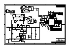
Figure 1. Input Buffer, Bipolar Fully Differential Input
Table 2. Analog Circuitry Jumper Configurations
Reference
1-2
2-3
Description
Designator
SJP1
Installed†
(1)
Not Installed
Select onboard reference (REF3230).
Not Installed
Installed
Select user-supplied reference at P1 pin 20.
SJP2
Installed†
(1)
Not Installed
Set REFIN pin of ADS8472 to on-chip (internal) reference voltage.
Not Installed
Installed
Set REFIN pin of ADS8472 to reference selected by SJP1.
SJP3
Installed
Not Installed
Set U6 operational amplifier minus rail supply to ground.
Not Installed
Installed†
(1)
Set U6 operational amplifier minus rail supply to –VCC.
SJP4
Installed
Not Installed
Set U7 operational amplifier minus rail supply to ground.
Not Installed
Installed†
(1)
Set U7 operational amplifier minus rail supply to –VCC.
SJP5
Not Installed
N/A
Short voltage node –DC to U6 pin 2 via R35.
SJP6
Not Installed
N/A
Short –IN pin of U5 to ground at C45.
(1)
† Indicates factory installed option.
The ADS8472 can operate with an external reference voltage in the range of 3.0V up to 4.2V. It generates
an on-chip 4.096V reference voltage. The ADS8472EVM allows the user to select the external reference
voltage from three sources. The first option is to use the internally generated 4.096V from the ADC. The
other two options are to select from the on board reference (U1) or a user supplied voltage applied at pin
20 of P1. Refer to
for solder jumper options for selecting from the various reference sources.
4
ADS8472EVM
SLAU203 – February 2007


