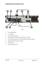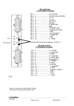
2. Backpanel layout description (see Fig.2)
REAR PANEL WITH OPT 34
IEE 488
ADDRESS
TERMINAL
TB3
TB4
6
5
1
3
8
4
7
2
-S -V +S +V
IEEE-488
RS232
(3,5mm Stereoklinkenbuchse)
S1 S2
Fig. 2
1
Power supply rearpanel
2
+/- Load terminals
3
AC input and main fuse (TB1)
4
Terminal block for +/- sense line and output vV, -V (TB2)
5
Opt 34, IEEE bus interface connector, address switches and RS-232 connector
6
Regulation board with TB3, TB4, S1 and S2
7
Grounding screw
8
Blind frame for switch S1/S2
Argos 500
Page
5
von
16
ISSUE
07/05


