TI4400 GPU-24
8
2
Product Overview
Full Charge
Half Charge
No Charge
STATUS
STATUS
STATUS
R
Y
G
0
1/2
OK
R
Y
G
0
1/2
OK
R
Y
G
0
1/2
OK
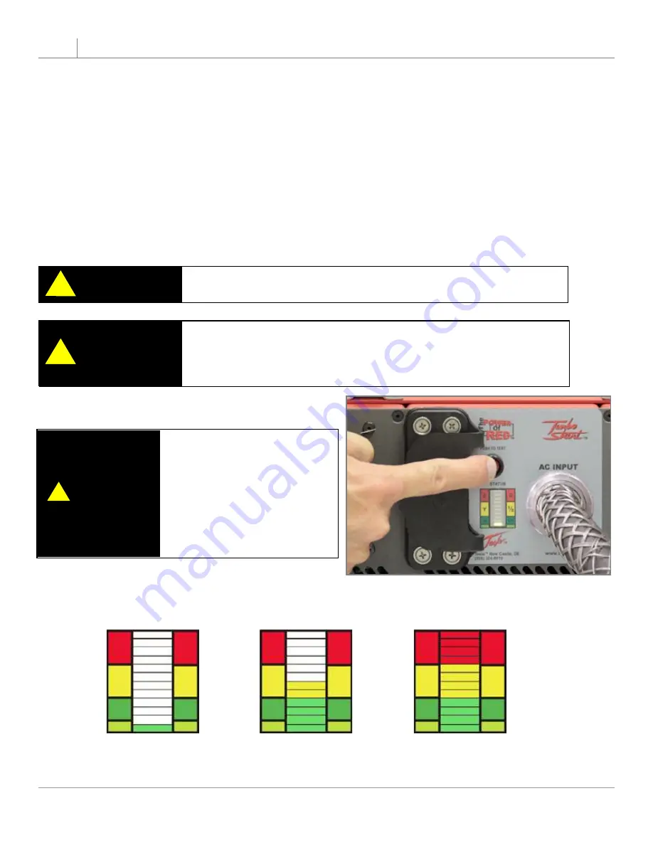
2.11 – “Push to Test” Button and LED Status Indicator
The “Push to Test” button indicates the capacity of the power cells without applying ac input power. The status
of the capacity lets the user know if there is enough power to perform another engine start. When the capacity is
low the unit should be connected to ac power to allow it to recharge.
Make sure that you wait at least 2 minutes after ac power is applied, or dc power is extracted from
1.
the unit, before you press the “Push to Test” button. This ensures a correct reading.
Without ac power input or dc power output, simply press the “Push to Test” button on the faceplate
2.
and hold for approximately 2 to 3 seconds.
The LED bar graph should light up indicating the status of the power cells.
3.
In addition, the fan(s) should start operating when the button is pressed. If you do not hear the
4.
fan(s) running, stop pressing the button and check for any obstructions.
CAUTION
!
Never press the “Push to Test” button while the unit is plugged into
aircraft, vehicle or ac power.
CAUTION
!
Never press the “Push to Test” button for more than 5 seconds. This
may cause a temperature sensor to temporarily disrupt “Push to
Test” function. (If this sensor is tripped, allow ten minutes for unit to
cool before operating “Push to Test” button.)
2.8 – “Push to Test” Button and LED Status Indicator
If unit is left charging after the
batteries are fully charged, the
unit will enter a
standby mode
.
The voltage will drop from
28.60 to 28.10 volts (±0.10).
When a load greater than 2
amps is applied, the unit will
return to normal operation.
NOTE
!
Figure 2.8.1 - “Push to Test” button


