background image

i

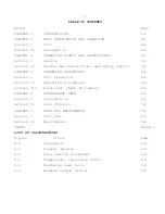
TABLE OF CONTENTS

TITLE

Page

CHAPTER 1

INTRODUCTION

1-1

CHAPTER 2

UNIT DESCRIPTION AND OPERATION

2-1

Section I

Unit

2-1

Section II

Description

2-2

CHAPTER 3

OPERATING LIMITS AND RESTRICTIONS

3-1

Section I

General

3-1

Section II

Operational Restrictions and Safety Limits

3-1

CHAPTER 4

OPERATING PROCEDURES

4-1

Section I

Unit  Operation

4-1

Section II

Operating Procedures

4-2

Section III

Functional Check Procedures

4-5

CHAPTER 5

PERFORMANCE DATA

5-1

Section I

Introduction

5-1

Section II

Data Criteria

5-2

CHAPTER 6

CARE AND MAINTENANCE

6-1

Section I

Unit Care

6-1

Section II

Maintenance

6-2

INDEX

Index 1

LIST OF ILLUSTRATIONS

Figure

Title

Page

2-1

Dimensions

2-3

2-2

General Details

2-2

2-3

Fuse Setting Procedures

2-4

5-1

Temperature Conversion Chart

5-3

5-2

Discharge Load Curve

5-4

5-3

Maximum Output Current

5-5

Содержание TI2000 GPU-24

Страница 1: ... 012 3 45 6 7 8 9 3 02 1 1 A BCD201 4E5 1 A BCD20 F G www TESLAind com TI2000 GPU 24 ...

Страница 2: ...OINT BLVD CENTERPOINT INDUSTRIAL PARK NEW CASTLE DELAWARE 19720 PH 302 324 8910 FAX 302 324 8912 WARNING SHOCK HAZARD POTENTIAL ATTEMPTS TO OPEN OR ENTER THE INSIDE OF THIS UNIT BY USING ANY TOOL OR DEVICE i e PROBE BORESCOPE etc CAN RESULT IN UNIT FAILURE AND OR POSSIBLE INJURY BY ELECTRICAL SHOCK THIS UNIT IS MAINTENANCE FREE AND SHALL NOT BE OPENED OR DISASSEMBLED FOR ANY REASON SHIPPING HAZARD...

Страница 3: ... 1 Section I Unit Operation 4 1 Section II Operating Procedures 4 2 Section III Functional Check Procedures 4 5 CHAPTER 5 PERFORMANCE DATA 5 1 Section I Introduction 5 1 Section II Data Criteria 5 2 CHAPTER 6 CARE AND MAINTENANCE 6 1 Section I Unit Care 6 1 Section II Maintenance 6 2 INDEX Index 1 LIST OF ILLUSTRATIONS Figure Title Page 2 1 Dimensions 2 3 2 2 General Details 2 2 2 3 Fuse Setting P...

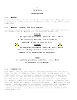
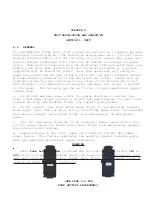
Страница 4: ...f equipment NOTE An operating procedure condition etc which is essential to highlight 1 3 DESCRIPTION This manual contains the complete operating instructions and proce dures for the TI2000GPU 24 Turbo Start 2000 ground power unit The Turbo Start 2000 is intended to provide DC electrical ground power for aircraft flight line and maintenance ground support operations The unit is designed to provide...

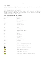
Страница 5: ...his manual LIST OF ABBREVIATIONS AND SYMBOLS Abbreviation Definition amp Ampere AC Alternating Current C Celsius cont Continuous DC Direct Current F Fahrenheit Ft Feet FWD Forward GPU Ground Power Unit Hr Hour Hz Hertz Kg Kilograms Kw Kilowatts Degree LED Light Emitting Diode MAX Maximum MIN Minimum VAC Volts Alternating Current VDC Volts Direct Current Explosion Hazard Potential Shock Hazard Pote...

Страница 6: ...D AND MAY Within this technical manual the word shall is used to indicate a mandatory requirement for proper operation and warranty purposes The word should is used to indicate a non mandatory but preferred method of accomplishment The word may is used to indicate an ac ceptable method of accomplishment ...

Страница 7: ... s four 4 main operational support capabilities a 24 VDC 3000 amp peak power output for engine starting or constant one hour rated power output without a 120 240 VAC power source for short term trouble shooting and flexible flight line support ground power b 24 VDC constant one hour rated power output or variable high load de mand output less than one hour with a 120 240 VAC power source for exten...

Страница 8: ...NORTH AMERICAN LINE CORD 105 125 VAC 60 Hz 6 50 amps max TI25000 U04 OLD BRITISH LINE CORD 210 250 VAC 50 60 Hz 3 25 amps max TI25000 U03 EUROPEAN 10A 250V 210 250 VAC 50 60 Hz 3 25 amps max TI25000 U05 ENGLAND 10A 250V 210 250 VAC 50 60 Hz 3 25 amps max OUTPUT POWER DC CONVERTER 28 5 VDC TO 20 AMPS 24 VDC 21 AMPS AND ABOVE POWER CELLS 24 VDC PEAK OUTPUT 3000 AMPS POWER CELL DRY HIGH RATE DISCHARG...

Страница 9: ...2 3 ...

Страница 10: ...from the fuse clip 6 Ensure that the proper voltage is selected on the white clip See Enlargement 2 3 1 Grab both tabs on left and right side of the fuse clip Press tabs inward and pull fuse clip out of housing GENTLY 2 Completely pull fuse clip from housing being careful not to drop the fuses from the fuse clip 3 Note The fuses are not fastened into the fuse clip they are lose Take care to ensure...

Страница 11: ...s will ensure that own ers operators obtain maximum continued capability from the Turbo Start 2000 ground power unit SECTION II OPERATIONAL RESTRICTIONS AND SAFETY LIMITS 3 3 POWER CELL RECHARGE LIMITS Any time the unit s power cells are fully discharged the unit shall be recharged within 24 hours to prevent performance degradation and ensure maximum life CAUTION Unit s power cells may be damaged ...

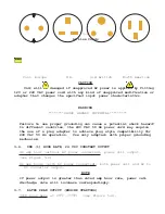
Страница 12: ... when con verter power output is no longer required Once DC power demand is terminated the unit s intelligent charger will remain on line to ensure power cells are charged to maximum capacity CAUTION Unit will be damaged if unapproved AC power is applied 3 5 AC POWER CORD LIMITS The AC power cord governs which AC power source the unit is set to operate from The Turbo Start 2000 is supplied with a ...

Страница 13: ...C 50 Hz power cord may require the use of a plug adapter to achieve plug style compatibility for 240 VAC 50 Hz operation Use only adapters with proper grounding mechanism 3 6 ONE 1 HOUR RATE 24 VDC CONSTANT OUTPUT 46 amp hour without AC power connected power cell output see Figure 5 2 66 amp hours with AC power connected both power cell and AC to DC converter output NOTE If power output is greater...

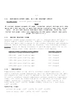
Страница 14: ...ower for an ef ficient engine start under specific current load demands ENGINE START CURRENT LOAD DEMAND MINIMUM CHARGE 650 850 peak starting amps 40 charged 850 1000 peak starting amps 50 charged 1000 1500 peak starting amps 60 charged 1500 1800 peak starting amps 70 charged 1800 2500 peak starting amps 80 charged 2500 3000 peak starting amps 90 charged 3 10 TEMPERATURE Temperatures refer to the ...

Страница 15: ...ential for equipment damage Every effort has been made within the scope of existing technology to prevent foreseeable safety hazards and make the Turbo Start 2000 moisture resistant to prevent damage or failure If the Turbo Start 3000 is exposed to moisture preventive measures and precautions shall be taken to a prevent accumulation of moisture on AC and DC con nectors receptacles b minimize moist...

Страница 16: ... be restricted to use without 120 or 240 power cord DO NOT CONNECT 120 or 240 VAC power cord until unit has been dried for a MINIMUM of one 1 hour prior to use Blowing sand or dust Minimize exposure to sand and dust when 120 240 AC power is used Unit shall be kept horizontal dur ing use 3 12 OPERATING POSITION Without 120 240 VAC power cord Horizontal or vertical Horizontal only for propper unit v...

Страница 17: ...utput is restricted to 24 VDC power cell output only DO NOT CONNECT 120 or 240 VAC POWER SUPPLY 120 240 VAC power charger or AC DC converter functions of unit shall not be oper ated during any aircraft fuel handling operation WARNING FIRE EXPLOSION HAZARD POTENTIAL Severe injury or Death may occur from fire or explosion as a result of electrical sparks produced near fuel vapors ...

Страница 18: ...of the unit 4 2 OPERATING LIMITS AND RESTRICTIONS The minimum maximum and normal operating ranges result from careful engineering and evaluation of test data These limitations must be adhered to during all phases of operation Refer to Chapter 3 Sec tion II OPERATING LIMITS AND RESTRICTIONS for detailed information 4 3 PERFORMANCE Refer to Chapter 5 PERFORMANCE DATA to determine the capability of t...

Страница 19: ...MBER when the AC line cord is plugged in the unit must be placed in the horizontal position to allow the cooling fan to operate properly 4 5 BEFORE OPERATION CHECK 1 CHECK FUSE WINDOW FOR PROPER SETTING 120 240 BEFORE PLUGGING UNIT INTO THE AC POWER SOURCE TO BE USED REMEMBER when the AC line cord is plugged in the unit must be placed in the horizontal posi tion to allow the cooling fan to operate...

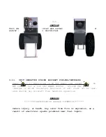
Страница 20: ... DC SYSTEM POWER 1 TRANSPORT UNIT The Turbo Start 2000 is easily transported using the wheels that are incorparated into the unit The AXEL EXTENTION kit included with the unit ensures that the Turbo Start 2000 is stable The unit is engineered to be pushed rather than pulled 2 CONNECT DC POWER CABLE TO UNIT Ensure power cable connector is fully seated into unit s connector Set the unit down horizon...

Страница 21: ...indicator and cooling fan are operational prior to continuing to step 3 3 CONNECT DC POWER CABLE TO UNIT Ensure power cable connector is fully seated into unit s receptacle 4 CONNECT DC POWER CABLE TO AIRCRAFT Connect to aircraft ground power receptacle DC bus power should come on and aircraft volt meter should indicate 27 5 VDC to 23 5 VDC 23 VDC minimum If cur rent demand is above 20 amps conver...

Страница 22: ...NIT Ensure power cable connector is fully seated into unit s receptacle 4 CONNECT DC POWER CABLE TO AIRCRAFT Connect to aircraft ground power receptacle DC bus power should come on and aircraft volt meter should indicate 28 5 VDC to 27 VDC 26 5 VDC minimum If air craft power demand is less than 20 amps converter output will remain at 28 5 VDC only one GREEN LED status indicator bar will illumi nat...

Страница 23: ...should show a single steady or flashing green LED bar when fully charged the last LED bar AC power may be left con nected to unit when power cells are fully charged NOTE Under a full charge two things will be observable with the unit A non blinking lighted green bar or a blinking green bar at the bottom of the bar graph both indicate a full charge Also the fan will dis play ratcheting but not come...

Страница 24: ...t proceed to step two IF DAMAGE IS EVIDENT contact distributor or manufacturer 2 ENSURE UNIT IS NOT PLUGGED INTO 120 OR 240 VDC Unplug AC power if plugged in 3 CHECK UNIT INTERNAL RESISTANCE TEST FOR SHORTS Better than 10 Megohms Ensure no short exists Negative DC receptacle terminal and unit case Positive DC receptacle terminal and unit case 4 CHECK DC VOLTAGE READING AT DC RECEPTACLE TERMINALS 2...

Страница 25: ...nder a full charge the last green LED bar may blink This does not indicate a malfunction A nonblinking lighted green bar or a blinking green bar at the bottom of the LED column both indicate a full charge 7 CHECK DC VOLTAGE READING AT DC RECEPTACLE TERMINALS Ensure power cells are fully charged see step 6 28 5 0 57 VDC with power cells at full state of charge 8 FUNCTIONAL CHECK COMPLETE Unit shoul...

Страница 26: ...readily recognize situations requiring maximum performance c To gain experience in accurately estimating the effects of variables for which data is not presented d To help the operator determine if an aircraft system malfunc tion exists by comparing actual performance with expected perfor mance NOTE The information provided in this chapter is primarily intended for operational planning and is most...

Страница 27: ...phys ics mathematics and electrical engineering principles and con cepts but not verified by tests 5 4 SPECIFIC CONDITIONS The data presented are accurate only for specific conditions listed under the title of each chart or graph Variables for which data are not presented but which may affect that phase of performance are discussed in associated text Where data are available or reasonable estimate...

Страница 28: ...ot account for instrument toler ance differences or inaccuracies 5 6 DEFINITIONS OF ABBREVIATIONS Unless otherwise indicated the abbreviations defined in Chapter 1 will be applicable to all charts and graphs in this chapter 5 2 FIGURE 5 1 ...

Страница 29: ...5 3 FIGURE 5 2 TI2000GPU 24 OUTPUT VOLTAGE OUTPUT VOLTAGE MINUTES 46 AMP CONSTANT CURRENT LOAD 24 20 16 12 8 4 0 0 10 20 30 40 50 60 ...

Страница 30: ... 5 3 0 0 300 600 900 1200 1500 1800 2100 3000 2700 2400 5 10 15 20 25 30 25 C Temp 29 C Temp Calculations based on actual test data at Pratt Whitney Canada on 30 March 1992 SECONDS AMPS MAXIMUM OUTPUT CURRENT 0 0 ...

Страница 31: ... wipe with dry cloth 2 KEEP FOREIGN OBJECTS OUT OF UNIT Cover unit to prevent foreign objects water and dirt from entering vent ports and recep tacles 3 KEEP FROM PROLONGED EXPOSURE TO EXTREMELY DAMP ENVIRONMENTS Cover unit to prevent migration of moisture If unit is operated in extremely damp environments unit should be kept in an environmentally controlled building 4 KEEP UNIT PLUGGED INTO AC PO...

Страница 32: ...ENANCE OF UNIT The Turbo Start 2000 is a maintenance free unit no repairs are authorized Warranty will be void if unit is tampered with If unit fails to operate contact Manufactures War ranty Claim see unit warranty WARRENTY VOID STICKERS ...

Страница 33: ...RACTED FROM THE UNIT BEFORE YOU DEPRESS THE PUSH TO TEST BUTTON THIS WILL ENSURE A CORRECT READING 2 WITHOUT AC POWER INPUT OR DC POWER OUTPUT SIMPLY DEPRESS THE PUSH TO TEST BUTTON ON THE FACE PLATE AND HOLD FOR APPROXIMATELY 15 SECONDS 3 AT THIS TIME THE LED BAR GRAPH SHOULD LIGHT UP INDICATING THE STATUS OF THE POWER CELLS 4 THE FAN SHOULD ALSO OPERATE AT THIS TIME IF YOU DO NOT HEAR THE FAN RU...

Страница 34: ...rd Limits 3 5 After Use 6 2 Appendix A Line Cord Table Before Operation Check 4 5 Continuous Output Rate 28 5 VDC Constant Output 3 8 Data Basis 5 3 DC Functional Check 4 12 Definitions of Abbreviations 5 6 Dimensions Figure 2 1 Discharge Load Curve Figure 5 2 Description 1 3 Engine Starting Power 3 9 Environmental 3 11 Functional Check Procedures 4 10 Forms and Records 1 6 General Chapter 1 1 1 G...

Страница 35: ... 12 Performance 4 3 Power Cell Recharge 4 9 Power Cell Recharge Limits 3 3 Purpose Chapter 3 3 1 Purpose Chapter 5 5 1 Rated Peak Output Engine Starting 3 7 Required Equipment for Functional Check 4 11 Specific Conditions 5 4 Temperature 3 10 Temperature Conversion Chart Figure 5 1 Unit Operation During Aircraft Fueling Defueling 3 13 Use of Word Shall Should and May 1 7 Warning Caution and Notes ...

Страница 36: ...roplug Line Cord Set Burma Now Myanmar 230 50 TI25000 005 United Kingdom Line Cord Set Burundi 220 50 TI25000 003 Cont European Line Cord Set Cambodia 220 50 TI25000 100 Europlug Line Cord Set Cameroon 230 50 TI25000 003 Cont European Line Cord Set Canada 120 60 TI25000 001 North American Line Cord Set Canary Islands Spain 220 b TI25000 003 Cont European Line Cord Set Cape Verde Rep of 220 50 TI25...

Страница 37: ...ont European Line Cord Set Guam 110 120 60 TI25000 001 North American Line Cord Set Guatemala 120 60 TI25000 001 North American Line Cord Set Guinea 220 50 TI25000 003 Cont European Line Cord Set Guinea Bissau 220 50 TI25000 003 Cont European Line Cord Set Guyana 110 50 60 TI25000 001 North American Line Cord Set Haiti 110 120 50 60 TI25000 001 North American Line Cord Set Honduras 110 60 TI25000 ...

Страница 38: ...gdom Line Cord Set Morocco 220 50 TI25000 003 Cont European Line Cord Set Mozambique 220 50 TI25000 003 Cont European Line Cord Set Namibia W S Africa 220 250 50 TI25000 004 Old British Line Cord Set Nepal 220 50 TI25000 004 Old British Line Cord Set Neth Antilles 220 50 60 TI25000 003 Cont European Line Cord Set Netherlands 220 50 TI25000 003 Cont European Line Cord Set New Caledonia 220 50 TI250...

Страница 39: ... Line Cord Set Sweden 220 50 TI25000 003 Cont European Line Cord Set Switzerland 220 50 TI25000 006 Switzerland Line Cord Set Syria 220 50 TI25000 100 Europlug Line Cord Set Tahiti 220 50 TI25000 003 Cont European Line Cord Set Taiwan 110 60 TI25000 001 North American Line Cord Set Tanzania 230 50 TI25000 005 United Kingdom Line Cord Set Thailand 220 50 TI25000 100 Europlug Line Cord Set Togo 220 ...

Страница 40: ...MAY BE RETURNED TO TESLA INDUSTRIES FOR A NOMINAL COST AND MODIFIED TO ALLOW OPERATION WITH THE UNIVERSAL AC LINE CORD KIT TESLA UNIVERSAL AC LINE CORD KIT P N TI25000 U00 IS COMPRISED OF THE FOLLOWING FOUR PART NUMBERS TI25000 U01 NORTH AMERICAN LINE CORD TI25000 U04 OLD BRITISH LINE CORD TI25000 U03 EUROPEAN 10A 250V TI25000 U05 ENGLAND 10A 250V TESLA REPLACEMENT 8 FOOT DC POWER CORD P N TI2006 ...

Отзывы: