


T-100 Series UPS User Manual
4
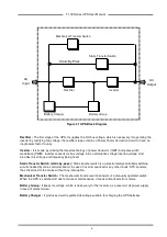
Rectifier :
The first stage of the UPS. It supplies the DC bus voltage, which is necessary for operating the
inverter by rectifying line voltage. the rectifier stage contains a Power Factor Correction circuit to have an
input power factor to unity.
Inverter :
It is made by utilizing the latest technology of power transistor (IGBT) and pulse width
modulation (PWM). Inverter converts dc bus voltage into an alternative voltage like line voltage. And
provides this voltage and frequency being fixed.
Static Transfer Switch (static by-pass) :
Static transfer switch is an electronically controlled switching
circuit checked by main controller board. In case of inverter overload or any other faults, STS transfers
the critical load to the mains without any interruption.
Mechanical Transfer Switch :
The mechanical transfer switch consists of a manually operated switch.
When the UPS is switched off due to failure or maintenance, it feeds critical loads from mains.
Battery Group :
It keeps dc voltage, which is necessary for the inverter, as a reservoir dc power supply
in case of mains failure.
Battery Charger :
It produces a well regulated dc voltage suitable for charging the UPS batteries.
Figure 2.1 UPS Block Diagram
Inverter
Rectifier
Static By-Pass
Static Transfer Switch
Mechanical Transfer Switch
AC
Input
AC
Output
Battery Group
Battery Charger
Содержание T-100 Series
Страница 2: ......
Страница 4: ......
Страница 19: ...T 100 Series UPS User Manual 16...
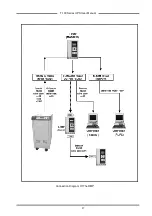
Страница 20: ...T 100 Series UPS User Manual 17 Connection Diagram Of The RMP COM1 T MON...
Страница 23: ...AGKK3772 02 2011...