MAINTENANCE
2-3
Page 2
TESCO EQUIPMENT LLC
ML50-30 MAINTENANCE LIFT
1.
INTRODUCTION
The Tesco ML50-30 Lift is a hydraulically operated, electrically controlled maintenance lift. The
hydraulic and electrical systems require a thorough understanding to determine the cause of a
malfunction or failure of a component. System diagnosis is mandatory to locate a component that is out
of adjustment or has failed.
2.
HYDRAULIC SYSTEM
1.
The hydraulic system is an open-center system.
2.
The hydraulic system diagnosis is accomplished by observing the readings on the pressure
gauge or timing a function when a particular hydraulic circuit is actuated. The hydraulic
schematics and adjustment procedures indicate the correct setting for each pressure and flow
adjustment.
3.
The first step in diagnosing a malfunction is to isolate the malfunction to the hydraulic system or to
the electrical control system.
NOTE:
All solenoid actuated control valves in the hydraulic system are equipped with a manual
override that can be used to actuate the valve should there be a loss of electrical current.
The manual override shifts the valve spool and permits oil flow for the Hi-Lift function to
operate. The pressure gauge can be observed for the correct pressure reading for the
system in use.
NOTE:
To obtain oil flow the PTO must be activated with the ENABLE switch. Alternatively, for
test or emergency operation, the hand pump or optional electric auxiliary hydraulic pump
may be used to provide hydraulic flow.
Press both UP switches simultaneously if not equipped with an ENABLE switch. In this
case one of the UP switches function as the ENABLE switch.
3.
ELECTRICAL SYSTEM
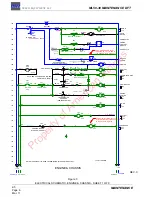
The Model ML50-30 has a 12-volt DC electrical system that controls all functions of the Hi-lift. The
components of the electrical system are located in the lower control station, the upper control station,
and the main electrical box. Limit switches in various locations sense a specific position of a mechanical
component for the actuation and interlocking of electrical circuits. The electrical box is located below the
van body usally on the passenger’s side mounted on the hydraulic module. It consists of relays, diodes,
circuit breakers, and terminal blocks. See Chapter 1, Section 2 for the location and function of each of
the separate control stations.
4.
TROUBLESHOOTING GUIDE
The following guide lists Hi-Lift malfunctions and some possible causes for those malfunctions. When
there is a problem or malfunction of the Hi-Lift, read through the list on the left side of the chart. Possible
causes are listed to the right.
Hydraulic component problems are usually caused by oil contamination, and many components can be
made serviceable by a thorough cleaning. Hydraulic filter elements must be replaced when a system
has been cleaned of contamination.
Hydraulic troubleshooting can be done using a pressure gauge and the hydraulic schematics.
Apr. 17
Property of American Airlines


