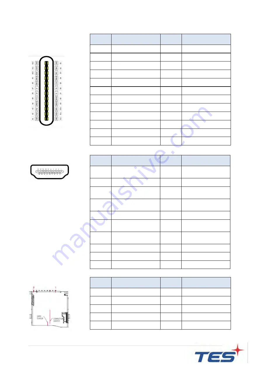
TES IEC-22A2 Скачать руководство пользователя страница 13


12

 |


HDMI   


TF card


Pin # 

Signal Name 

Pin # 

Signal Name 


DAT2 

DAT3 

CMD 

VCC 

CLK 

GND 

DAT0 

DAT1 

CD 


USB-C 

Pin # 

Signal Name 

Pin # 

Signal Name 


A1 

GND 

B12 

GND 

A2 

SSTXp1 

B11 

SSRXp1 

A3 

SSTXn1 

B10 

SSRXn1 

A4 

VBUS 

B9 

VBUS 

A5 

CC1 

B8 

SBU2 

A6 

Dp1 

B7 

Dn2 

A7 

Dn1 

B6 

Dp2 

A8 

SBU1 

B5 

CC2 

A9 

VBUS 

B4 

VBUS 

A10 

SSRXn2 

B3 

SSTXn2 

A11 

SSRXp2 

B2 

SSTXp2 

A12 

GND 

B1 

GND 

Pin # 

Signal Name 

Pin # 

Signal Name 

TMDS Data2+ 

TMDS Data2 

Shield 

TMDS Data2- 

TMDS Data1+ 

TMDS Data1 

Shield 

TMDS Data1- 

TMDS Data0+ 

TMDS Data0 

Shield 

TMDS Data0- 

10 

TMDS Clock+ 

11 

TMDS Clock 

Shield 

12 

TMDS Clock- 

13 

CEC 

(N.C on device) 

14 

Reserved 

(N.C. on device) 

15 

SCL 

16 

SDA 

17 

DDC/CEC Ground  18 

+5V Power 

19 

Hot Plug Detect 


Содержание IEC-22A2

Страница 1: ...IEC 22A2 Touch Computer User Manual Version 2 0 2020 10...

Страница 2: ...e information in this document is subject to change without notice TES makes no representations or warranties with respect to the contents herein and specifically disclaims any implied warranties of m...

Страница 3: ...ion manual may cause harmful interference to radio communications Operation of this equipment in a residential area is likely to cause harmful interference in which case the user will be required to c...

Страница 4: ...rasites nuisant aux communications radio L utilisation de ce mat riel dans une zone r sidentielle est susceptible de causer des parasites auquel cas l utilisateur est tenu de corriger le probl me des...

Страница 5: ...humid environment Areas susceptible to excessive dust and dirt Near any appliance generating a strong magnetic field Caution Risk of explosion if battery is replaced by an incorrect type Dispose of u...

Страница 6: ...dit des endroits remplis de poussi res et de salet s proximit d appareils produisant un fort champ magn tique Mise en garde Risque d explosion si la batterie est remplac e par un type incorrect Jetez...

Страница 7: ...18 2 3 2 System with Stand Module 19 2 4 Optional Accessory Installation 20 2 4 1 Install the Stand Module 20 2 4 2 Dismantle the Stand Module 20 2 4 3 Install the Cables 21 2 4 3 1 Cable Organizer 2...

Страница 8: ...7 Chapter 1 Product Introduction...

Страница 9: ...lementation 1 3 Specifications System CPU Rock chip RK3399 Dual core Cortex A72 up to 1 8GHz Quad core Cortex A53 up to 1 4GHz GPU Mail T860 MP4 Memory 2GB dual channel LPDDR4 Storage 16GB eMMC Input...

Страница 10: ...min 200 cd m2 Brightness P CAP with ZCC Typical 212 5 cd m2 min 170 cd m2 Brightness P CAP with TPK Typical 225 cd m2 min 180 cd m2 Number of Pixels 1920 H 1080 V 60Hz Tilt Angle 10 70 Environment Ce...

Страница 11: ...10 1 4 Block Diagram...

Страница 12: ...2V 2 GND RJ45 for LAN Pin Signal Name Pin Signal Name 1 TP1 2 TP1 3 TP2 4 TP3 5 TP3 6 TP2 7 TP4 8 TP4 LED Function Color Left Active Yellow Blink Right 10M 100M 1000M Green USB3 0 Pin Signal Name Pin...

Страница 13: ...B7 Dn2 A7 Dn1 B6 Dp2 A8 SBU1 B5 CC2 A9 VBUS B4 VBUS A10 SSRXn2 B3 SSTXn2 A11 SSRXp2 B2 SSTXp2 A12 GND B1 GND Pin Signal Name Pin Signal Name 1 TMDS Data2 2 TMDS Data2 Shield 3 TMDS Data2 4 TMDS Data1...

Страница 14: ...ration 3048m minimum If it needs further assistance with purchasing the power source please contact to TES for further information Mise en garde Cet appareil est con u avec une alimentation de courant...

Страница 15: ...14 Chapter 2 Product Installation...

Страница 16: ...unting for horizontal output connector facing down and vertical mounting orientations output connector facing left or right when EUT without base The equipment with base used for horizontal output con...

Страница 17: ...distance entre la surface du couvercle arri re et le bas de l orifice de la vis est de 8 mm Utiliser quatre vis M4 de 8 mm de diam tre pour le montage de votre moniteur Remarque Le support de montage...

Страница 18: ...h Power On Off Switch Function Description Power on Press the power button 2 sec Sleep Press the power button to enter sleep mode and press again to resume from sleep Power off Press the power button...

Страница 19: ...18 2 3 Dimension 2 3 1 System Only Front View Side View Rear View Bottom View...

Страница 20: ...19 2 3 2 System with Stand Module Front View Side View Rear View Bottom View...

Страница 21: ...in the shutdown state 2 4 1 Install the Stand Module Place stand module on back of touch computer and align the screw holes Install the four M4 screws to fasten the stand 2 4 2 Dismantle the Stand Mod...

Страница 22: ...nizer Step 1 Pull down the cable cover for cables installation Step 2 To fit the plugs Step 3 To assemble the cable cover Step 4 Driving a screw to fix cable cover The cable can be fixed above or belo...

Страница 23: ...4 4 Install the Camera Module Camera Module max 19g Step 1 Remove the side cover Step 2 Connect the camera module cable to the touch computer Step 3 Install the two M3 screws to fasten the camera mod...

Страница 24: ...ep 2 Remove the camera module cable from the touch computer Step 3 To assemble the side cover 2 4 6 Install the MSR Module MSR Module max 62g Step 1 Remove the side cover Step 2 Connect the MSR module...

Страница 25: ...24 Step 3 The metal bracket hook into the gap between cover glass and bezel Step 4 Install the two M3 screws to fasten the MSR module Step 4...

Страница 26: ...25 2 4 7 Dismantle the MSR Module Step 1 Loosen the screws Step 2 Remove the MSR module cable from the touch computer Step 3 To assemble the side cover Step 1 Step 3 Step 2...

Страница 27: ...26 Appendix...

Страница 28: ...inated diphenyl ethers PBDE Plastic Parts Metal Parts Cable component LCD Panel Touch Panel PCBA Software Note 1 Exceeding 0 1 wt and exceeding 0 01 wt indicate that the percentage content of the rest...

Отзывы: