5
Device information table
This shows the data of module:
"Device model": model of the module.
"Serial number": serial number of the module.
"Software version": module software version number.
"Hardware version": module hardware version number.
"IP 1": IP address of the control interface.
"IP 2": IP address of the streaming interface.
"System time": current time, synchronized from the TDT table of the input stream. Local time offset can be selected in
the "IP settings" tab, see section
7.5
.
"Up time": time passed from last power-up or restart of the module.
In the "Common status" table the following parameters are displayed at real time: input bit rate in kbps, output bit rate in
kbps, processor load in percents, internal temperature in degrees of Celsius, power voltage in Volts.
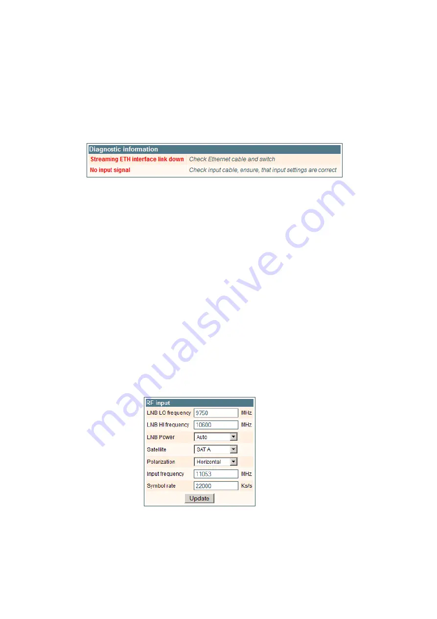
In the "Diagnostic information" table all module errors and comments how to eliminate these errors are displayed.
Figure 8. Diagnostic information table with errors
7.3 Input settings
This screen consists of three tables: "RF input", "List of services" and "Input status". The "RF input" table is used to configure
parameters corresponding to the input satellite transponder (sdi410C, sda410C module), terrestrial or cable transponder
(sti410C, sta410C module), DVB-ASI transponder (sai410C, saa410C module). In the "List of services" table the list of services,
available in the input transponder is displayed. In the "Input status" table you can see real time status of the input section.
The "RF input" table is different according the input signal of module.
7.3.1. RF input table
The "RF input" table (Figure 9) for sdi410C, sda410C module consists of following parameters:
"LNB LO frequency" - the LNB local oscillator lower frequency in megahertz. Use 9750 MHz for the universal converter.
"LNB HI frequency" - the LNB local oscillator upper frequency in megahertz. Use 10600 MHz for the universal converter.
“LNB voltage” – power supply of the converter – can be set to “Off”, “Auto”, “13V”, “18V”, “13V/22kHz”, “18V/22kHz”. If
“Auto” is selected, power supply voltage of the converter is choosen according to set polarisation – 18V Horizontal, 13V
Vertical; if the “Frequency” of the satellite exceeds the value F=(950+LNB Hi+2150+LNB Lo)/2, the 22 kHz signal is switched
ON and “LNB Hi freq.” is selected.
For example
: LNB Hi=10,600, LNB Lo=9750, then F=(950+10,600+2150+9750)/2=11,725 MHz. When power supply of
the converter is set to value different from "Auto" - "LNB HI frequency", “Satellite”, "Polarisation" rows are disabled and the
"LNB LO frequency" value is used for IF frequency calculation.
“Satellite” – DISEQC command is used to select the satellite when the switch that supports DISEQC protocol is present.
Possible commands: “None”, “SAT A”, “SAT B”, “SAT C”, “SAT D”.
"Polarisation" - the polarisation of converter. Can be "Horizontal" or "Vertical".
“Frequency” - the frequency of the satellite transponder in megahertz.
“Symbol rate” - the symbol rate of the satellite transponder in kilo symbols per second.
Figure 9. The "RF input" table of the sdi410C, sda410C module
The "RF input" table (Figure 10) for sti410C, sta410C module consists of following parameters:
"Modulation standard" - used to select from the "DVB-T/T2" and "DVB-C" modulation standards.
"Preamplifier power" - used to switch on/off the power for the RF preamplifier.
"Input bandwidth" - the bandwidth of DVB-T/T2 transponder. Can be selected from values 8 MHz and 7 MHz.


