background image

Robot

5000 - 8000 - 15000

OPERATOR HANDBOOK

Code 57.0300.0200 - 4

th 

Edition 07/2000

CAUTION: THOROUGHLY READ AND UNDERSTAND THIS MANUAL BEFORE OPERATING THE MACHINE

CAUTION: KEEP THIS MANUAL IN THE MACHINE AT ALL TIMES

English

Edition

Содержание Robot 15000

Страница 1: ...00 15000 OPERATOR HANDBOOK Code 57 0300 0200 4th Edition 07 2000 CAUTION THOROUGHLY READ AND UNDERSTAND THIS MANUAL BEFORE OPERATING THE MACHINE CAUTION KEEP THIS MANUAL IN THE MACHINE AT ALL TIMES En...

Страница 2: ......

Страница 3: ...of constant quality improvement ITALMACCHINE S p A reserves the right to make changes at any time and without undertaking to give prior notice therefore also this publica tion may be subject to modifi...

Страница 4: ......

Страница 5: ...lothes 19 B 2 4 Personal protective equipment 19 B 3 SAFETY PRECAUTIONS 19 B 3 1 Working area 19 B 3 2 Getting ready to work 20 B 3 3 During work or maintenance 20 Section C OPERATING INSTRUCTIONS C 1...

Страница 6: ...Document 57 0300 0200 4th Edition 07 2000 Forl Page 2 Robot Intentionally blank page...

Страница 7: ...es the essential compulsory qualities of the personnel in charge and provides important informa tion for the safety of persons and things Section C is mainly addressed to the operators who shall opera...

Страница 8: ...ohibitions or pro vides instructions to prevent risks Sometimes texts can be followed by illustrations The special or safety symbols used in this manual ac cording to the seriousness of the hazard sit...

Страница 9: ...Document 57 0300 0200 4th Edition 07 2000 Forl Page 5 Robot Section A GENERAL INFORMATION...

Страница 10: ...ERENCES A 1 1 Machine position Conventionally the machine should be considered po sitioned as shown in figure A1 This convention is necessary to make any reference of this handbook to different machin...

Страница 11: ...to be re placed make sure that the new part is already la belled as required or apply a new label MAX PAYLOAD 200 kg OR 2 PERSONS IMPORTANT The work platform may be operated only when sta bilisers ar...

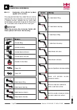
Страница 12: ...ith these symbols and to learn their meaning Handler lifting Handler lowering Handler boom extension Handler boom retraction Handler turret rotation Power ON Power OFF Robot boom lifting Robot boom lo...

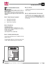
Страница 13: ...ia under the n 4823 C C I A A n 102886 Fiscal Code V A T no 00249210543 A 2 3 Machine identification plate The machine identification plate is applied within the platform Fig A1 The identification pla...

Страница 14: ...IFT 3013 GIROLIFT 3514 GIROLIFT 5022 Robot Robot Robot For machines 5000 8000 15000 with platform with platform with platform A 3 2 Improper use Improper use means a utilisation of the robot following...

Страница 15: ...board 3 Platform control board 4 Platform sway cylinder 5 Sway compensating cylinder 6 Boom rotation column 7 Boom extensible section only Robot 8000 8 Boom fixed section 9 Robot boom motion cylinder...

Страница 16: ...scopic boom 4 Platform linkage 5 Platform sway cylinder 6 Platform 7 1st boom 8 2nd boom cylinder 9 1st boom cylinder 10 Boom supporting column 11 Mobile frame 12 Support with platform rotation fulcru...

Страница 17: ...ing depth mm 3130 G Boom extension mm Technical data with reversed robot for jobs under the level surface H Reach at max height mm 3130 L Max height mm 290 M Reach at max depth mm 1710 N Max depth mm...

Страница 18: ...m extension mm 1600 Technical data with reversed robot for jobs under the level surface H Reach at max height mm 5430 L Max height mm 2260 M Reach at max depth mm 2690 N Max working depth mm 8950 Gene...

Страница 19: ...Document 57 0300 0200 4th Edition 07 2000 Forl Page 15 Robot E F B D A C H H M L N R G P A 5 3 Main dimensions Robot 15000 V Z U T S TECHNICAL DATA AND PERFORMANCE A Fig A8...

Страница 20: ...Max depth mm 13070 P Reach at max height mm 3270 R Max height mm 750 Technical data with robot set to road circulation configuration S Rotation axis to lifter hinge pin distance mm 600 T Rotation axis...

Страница 21: ...Document 57 0300 0200 4th Edition 07 2000 Forl Page 17 Robot Section B SAFETY...

Страница 22: ...the assistance serv ice is at your disposal Addresses phone fax and telex numbers are given in the cover and in the title page of this manual DANGER The operator on the platform must be assisted by su...

Страница 23: ...ts Operators should wear neither clothes with large sleeves nor objects that could get stuck in moving parts of the machine Protection helmet Protection gloves Working shoes Safety belt IMPORTANT Use...

Страница 24: ...ators stop the engine and step on the brake pedal 8 10 times Dot not smoke or use open flames in areas subject to fire dangers and in presence of fuel oil or batteries Do not leave fuel cans or bottle...

Страница 25: ...Document 57 0300 0200 4th Edition 07 2000 Forl Page 21 Robot Section C OPERATING INSTRUCTIONS...

Страница 26: ...required A IMPORTANT For the controls operated from the driving place of the handler please refer to the operator s handbook of the handler C 1 COUPLING THE ROBOT TO THE HANDLER To couple the robot t...

Страница 27: ...ROBOT PLATFORM To get access to the work platform raise the mobile guard A fig C6 C 2 1 FASTENING THE SAFETY BELTS IMPORTANT The platform is equipped for the installation of safety belts For their us...

Страница 28: ...platform Box A on the right hand side houses the handler controls Box B on the left hand side houses the robot controls To get access to the control levers on the platform raise the strip fitted prot...

Страница 29: ...tage key can be removed and engine is stopped Circuit under voltage all controls are ON Green button to start the engine White button to sound the horn Black button to operate the emergency pump SETUP...

Страница 30: ...old it pressed down until the end of the required motion If the button is not pressed down controls cannot be operated SETUP C 0 1 2 0 10 5 6 Knob adjusting the speed of the actuator motions The knob...

Страница 31: ...st lower the robot platform to the ground according to the specific procedure C 4 1 Switching the controls from handler to platform When the robot is correctly coupled to the handler and ready to work...

Страница 32: ...ep into the driving cab of the handler insert the key removed from the platform control board into the Cabin Road Platform switch and set it to the Cabin position the green lamp switches off CAUTION N...

Страница 33: ...this Presstheemergencystoppushbuttononthehandler control board PressthebuttonoftheemergencypumpA fig C15 while operating the control block levers to lower the platform to the ground For this operation...

Страница 34: ...m from boom and cylinder and refit it turned upside down Reverse the robot and re couple to the handler Refit the proximity switch of the attachment locking and fix it to the special hole then check t...

Страница 35: ...lug the power plug from the socket placed in the lower part of the control box Using the cable provided plug the previously re moved control box in the power socket placed closed to the branch box Low...

Страница 36: ...linder Turn the platform upside down Refit it to boom and cylinder using the previously removed pins CAUTION The platform weighs 40 kg and can be handled by two persons Use the special personal protec...

Страница 37: ...Document 57 0300 0200 4th Edition 07 2000 Forl Page 33 Robot Section D MAINTENANCE...

Страница 38: ...n In case of a prolonged contact wash with soap and water Fire In case of fire use carbon dioxide dry chemical or foam extinguishers Do not use water D 2 MAINTENANCE INTERVENTIONS A wrong or neglected...

Страница 39: ...e thoroughly clean the greas ers to avoid that mud dust or other matters can mix with the lubricant and reduce or even annihilate its effect Regularly grease the equipment to preserve it in good condi...

Страница 40: ...the tel escopic boom In the event an excessive play in the telescopic boom is noticed change the sliding blocks it is fitted with To this end To change the blocks from the fixed boom loosen screws A r...

Страница 41: ...chment locking control see operator s manual of the handler Ro tate the platform to both directions some times then stop it to perfectly vertical position Close the cocks and reconnect the hydraulic c...

Страница 42: ...er to platform Stabilisers are up Key switch A set to Cab controls Platform overload THE WORK PLATFORM CONTROLS DO NOT FUNCTION WARNING LAMP B fig C10 DOES NOT SWITCH ON ALARM SIGNALLED BY THE OVERLOA...

Отзывы: