December 2018
Service and Repair Manual
Manifolds
Part No. 1271125GT
Z®-60/37 DC • Z®-60
/37 FE
49
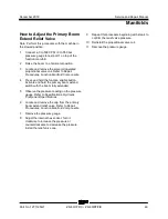
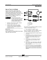
How t o Adj ust t he Pri mar y Boom Extend R elief Val ve
How to Adjust the Primary Boom
Extend Relief Valve
Note: Perform this procedure with the machine in
the stowed position.
1
Connect a 0 to 5000 PSI / 0 to 350 bar
pressure gauge to test port 1 on top of the
function manifold.
2
Raise the boom to a horizontal position.
3
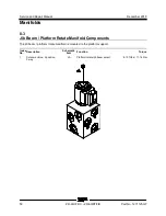
Locate and remove the solenoid operated
proportional valve coil. Refer to Repair
Procedures,
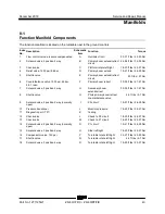
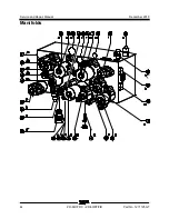
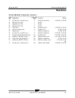
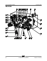
Function Manifold Components
.
4
Press and hold the function enable button.
Activate and hold the primary boom extend
switch with the boom fully extended.
5
Observe the pressure reading on the pressure
gauge. Refer to Specifications,
Hydraulic
Component Specifications
.
6
Locate and remove the cap from the primary
boom extend relief valve. Refer to Repair
Procedures,
Function Manifold Components.
7
Remove the pressure gauge.
8
Adjust the internal hex socket. Turn it
clockwise to increase the pressure or
counterclockwise to decrease the pressure.
Install the relief valve cap.
9
Repeat this procedure beginning with step 4 to
confirm the relief valve pressure.
10 Reinstall the proportional valve coil.
11 Remove the pressure gauge.
Содержание Genie Z-60 DC
Страница 54: ...Service and Repair Manual December 2018 Manifolds 44 Z 60 37 DC Z 60 37 FE Part No 1271125GT ...
Страница 56: ...Service and Repair Manual December 2018 Manifolds 46 Z 60 37 DC Z 60 37 FE Part No 1271125GT ...
Страница 104: ...Service and Repair Manual December 2018 CAN BUS Wiring Diagram DC Models 94 Z 60 37 DC Z 60 37 FE Part No 1271125GT ...
Страница 106: ...Service and Repair Manual December 2018 96 Z 60 37 DC Z 60 37 FE Part No 1271125GT This page intentionally left blank ...
Страница 107: ...December 2018 Service and Repair Manual 97 Wiring Diagram Options ...
Страница 108: ...Service and Repair Manual December 2018 98 Z 60 37 DC Z 60 37 FE Part No 1271125GT Wiring Diagram Options ...
Страница 110: ...Service and Repair Manual December 2018 100 Schematics Options 4WD DC and FE Models ...
Страница 111: ...December 2018 Service and Repair Manual 101 Power Cable Wiring Diagram ...
Страница 112: ...Service and Repair Manual December 2018 102 Z 60 37 DC Z 60 37 FE Part No 1271125GT Power Cable Wiring Diagram ...
Страница 113: ...December 2018 Service and Repair Manual 103 Hydraulic Schematic DC and FE Models ...
Страница 114: ...Service and Repair Manual December 2018 104 Z 60 37 DC Z 60 37 FE Part No 1271125GT Hydraulic Schematic DC FE Models ...
Страница 115: ...December 2018 Service and Repair Manual 105 Electrical Schematic DC FE Models ...
Страница 116: ...Service and Repair Manual December 2018 106 Z 60 37 DC Z 60 37 FE Part No 1271125GT Electrical Schematic DC FE Models ...
Страница 117: ...December 2018 Service and Repair Manual Part No 1271125GT Z 60 37 DC Z 60 37 FE 107 Electrical Schematic DC FE Models ...
Страница 118: ...Service and Repair Manual December 2018 108 Electrical Schematic DC FE Models ...
Страница 119: ...December 2018 Service and Repair Manual Part No 1271125GT Z 60 37 DC Z 60 37 FE 109 Electrical Schematic DC FE Models ...
Страница 120: ...Service and Repair Manual December 2018 110 Electrical Schematic DC FE Models ...
Страница 121: ...December 2018 Service and Repair Manual 111 Ground Control Box Terminal Strip Wiring Diagram DC FE Models ...
Страница 125: ......

