Service and Repair Manual
December 2018
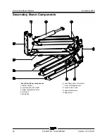
Secondary Boom Components
38
Z®-60/37 DC • Z®-60
/37 FE
Part No. 1271125GT
8
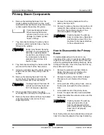
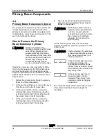
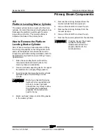
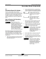
Lower the cylinder onto the lower compression
arm.
9
Remove the six fasteners securing the cap on
the rod-end of the lift cylinder through the
access hole of the lower compression arm.
Note: When installing the lift cylinder, torque the
cap fasteners to 110 ft-lbs / 149 Nm dry.
10 Lift and move the cylinder towards the center
of the machine enough to lower it down
through the lower compression arm. Pull the
cylinder towards the platform and remove it
from the machine.
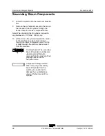
Crushing hazard. The secondary
boom lift cylinder could become
unbalanced and fall when
removed from the machine if not
properly attached to the
overhead crane.
Component damage hazard.
When removing a secondary
boom lift cylinder from the
machine, be careful not to
damage the counterbalance
valve at the barrel end of the
cylinder.
Содержание Genie Z-60 DC
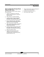
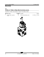
Страница 54: ...Service and Repair Manual December 2018 Manifolds 44 Z 60 37 DC Z 60 37 FE Part No 1271125GT ...
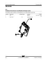
Страница 56: ...Service and Repair Manual December 2018 Manifolds 46 Z 60 37 DC Z 60 37 FE Part No 1271125GT ...
Страница 104: ...Service and Repair Manual December 2018 CAN BUS Wiring Diagram DC Models 94 Z 60 37 DC Z 60 37 FE Part No 1271125GT ...
Страница 106: ...Service and Repair Manual December 2018 96 Z 60 37 DC Z 60 37 FE Part No 1271125GT This page intentionally left blank ...
Страница 107: ...December 2018 Service and Repair Manual 97 Wiring Diagram Options ...
Страница 108: ...Service and Repair Manual December 2018 98 Z 60 37 DC Z 60 37 FE Part No 1271125GT Wiring Diagram Options ...
Страница 110: ...Service and Repair Manual December 2018 100 Schematics Options 4WD DC and FE Models ...
Страница 111: ...December 2018 Service and Repair Manual 101 Power Cable Wiring Diagram ...
Страница 112: ...Service and Repair Manual December 2018 102 Z 60 37 DC Z 60 37 FE Part No 1271125GT Power Cable Wiring Diagram ...
Страница 113: ...December 2018 Service and Repair Manual 103 Hydraulic Schematic DC and FE Models ...
Страница 114: ...Service and Repair Manual December 2018 104 Z 60 37 DC Z 60 37 FE Part No 1271125GT Hydraulic Schematic DC FE Models ...
Страница 115: ...December 2018 Service and Repair Manual 105 Electrical Schematic DC FE Models ...
Страница 116: ...Service and Repair Manual December 2018 106 Z 60 37 DC Z 60 37 FE Part No 1271125GT Electrical Schematic DC FE Models ...
Страница 117: ...December 2018 Service and Repair Manual Part No 1271125GT Z 60 37 DC Z 60 37 FE 107 Electrical Schematic DC FE Models ...
Страница 118: ...Service and Repair Manual December 2018 108 Electrical Schematic DC FE Models ...
Страница 119: ...December 2018 Service and Repair Manual Part No 1271125GT Z 60 37 DC Z 60 37 FE 109 Electrical Schematic DC FE Models ...
Страница 120: ...Service and Repair Manual December 2018 110 Electrical Schematic DC FE Models ...
Страница 121: ...December 2018 Service and Repair Manual 111 Ground Control Box Terminal Strip Wiring Diagram DC FE Models ...
Страница 125: ......

