background image

Service and Repair Manual


December 2019


Boom Components 


68 

SX

-150


Part No. 1300669GT 


4-7 

Boom Length Sensor 
How to Calibrate the Primary 

Boom Length Sensor 

Note: Perform this procedure with the machine on 

a firm, level surface with the axles extended. 
Note: The turntable level sensor and platform load 

sensor must be calibrated prior to calibrating the 

primary boom angle sensor. 
Note: LTB1LO and LTB1LS are calibrated at the 

same time. 
Note: The turntable level sensor, platform load 

sensor and primary boom angle sensor must be 

calibrated before calibrating the boom length 

sensor. 
Note: Platform leveling is set to default parameters 

to avoid platform out of level faults during 

calibration. 
Note: If the calibration flags between SCON and 

TCON do not agree after calibration, a crosscheck 

fault is generated and recorded and the affected 

boom function is inhibited. 


Note: Use the following chart to identify the 

description of each LCD screen control button used 

in this procedure. 


Plus 

Minus 

Previous 

Enter 

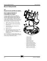
1  With the boom in the stowed position, start the 

engine and fully raise the boom to its 

maximum angle. 

2  Push in the ground controls red Emergency 

Stop button to the off position. 

3  Turn the key switch to ground controls. 
4  Open the ground control box. 
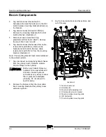
5  Locate the calibration toggle switch at the top 

of the ground control box. Activate calibration 

mode by moving the toggle switch in the left 

direction. 

6  Temporarily install a control box door retaining 

fastener between the door and the box to 

prevent the control box door from moving the 

toggle switch while calibrating the machine. 

7  Remove the key from the main key switch. 

Insert the key into the bypass/recovery key 

switch and turn it to the bypass position. 

Note: The length sensor calibration values will not 

be saved correctly unless the key switch is in the 

bypass / recovery position. 

Содержание Genie SX-150

Страница 1: ...e SX 150 from SX150H 612 This manual includes Repair procedures Fault Codes Electrical and Hydraulic Schematics For detailed maintenance procedures refer to the appropriate Maintenance Manual for your machine Part No 1300669GT Rev A December 2019 ...

Страница 2: ...ife Unrestricted with proper operation inspection and scheduled maintenance Technical Publications Genie has endeavored to deliver the highest degree of accuracy possible However continuous improvement of our products is a Genie policy Therefore product specifications are subject to change without notice Readers are encouraged to notify Genie of errors and send in suggestions for improvement All c...

Страница 3: ...ory Revision Date Section Procedure Page Description A 12 2019 Initial Release Reference Examples Electronic Version Click on any content or procedure in the Table of Contents to view the update Section Repair Procedure 4 2 Section Fault Codes All charts Section Schematics Legends and schematics ...

Страница 4: ...e and Repair Manual December 2019 Introduction iv SX 150 Part No 1300669GT Serial Number Legend 1 Model 2 Facility code 3 Sequence number 4 Serial label located under cover 5 Serial number stamped on chassis ...

Страница 5: ...y Many of the hazards identified in the operator s manual are also safety hazards when maintenance and repair procedures are performed Do Not Perform Maintenance Unless You are trained and qualified to perform maintenance on this machine You read understand and obey manufacturer s instructions and safety rules employer s safety rules and worksite regulations applicable governmental regulations You...

Страница 6: ...ushing hazards such as moving parts free swinging or unsecured components when lifting or placing loads Always wear approved steel toed shoes Workplace Safety Any person working on or around a machine must be aware of all known safety hazards Personal safety and the continued safe operation of the machine should be your top priority Be sure to keep sparks flames and lighted tobacco away from flamm...

Страница 7: ...on 2 Specifications 1 Machine Specifications 1 Performance Specifications 2 Hydraulic Oil Specifications 3 Hydraulic Component Specifications 6 Manifold Component Specifications 7 Deutz TD2011L04i Engine Specifications 8 Deutz TD 2 9 Engine Specifications 9 Perkins 1104D 44T Engine Specifications 10 Perkins 854F 34T Engine Specifications 12 Machine Torque Specifications 13 Hydraulic Hose and Fitti...

Страница 8: ...o Adjust the Function Ramp Rate Setting 28 Platform Components 29 2 1 Platform 29 2 2 Platform Leveling Cylinder 30 2 3 Platform Rotator 31 How to Bleed the Platform Rotator 32 2 4 Platform Level Sensor 33 2 5 Platform Overload System 34 How to Calibrate the Platform Overload System 34 How to Perform a Zero Load Cell Calibration 36 How to Replace the Platform Overload Load Cell 37 2 6 Platform Ove...

Страница 9: ...4 6 Primary Boom Angle Sensor 65 4 7 Boom Length Sensor 68 Engines 70 5 1 RPM Adjustment 70 5 2 Flex Plate 70 How to Install the Flex Plate 71 Ground Controls 72 6 1 Bypass Recovery Key Switch 72 How to Use the Recovery Mode 73 6 2 Circuit Boards 74 6 3 Membrane Decal 76 6 4 Full Machine Calibration 77 Display Module 78 Hydraulic Pumps 85 7 1 Function Pump 85 How to Prime the Function Pump 86 How ...

Страница 10: ...ifold 108 8 8 Traction Manifold Components 109 8 9 Valve Adjustments Traction Manifold 113 8 10 Generator Manifold Component 114 8 11 Valve Coils 115 Turntable Rotation Components 117 9 1 Turntable Rotation Assembly 117 How to Adjust the Turntable Rotation Gear Backlash 118 9 2 Turntable Level Sensor 119 Axle Components 122 10 1 Steer Sensors 122 How to Calibrate a Replacement Steer Sensor 124 How...

Страница 11: ...71 Section 5 Schematics 180 Introduction 180 Wire Circuit Legend 181 Wire Color Legend 185 Limit Switches and Angle Sensors 190 Circuit Connector Legend 194 Connector Pin Legend 197 Engine Relay and Fuse Panel Legend Deutz TD2011L04i and Perkins 1104D 44T Models 212 Engine Relay and Fuse Panel Legend Deutz TD 2 9 L4 Models 213 Engine Relay and Fuse Panel Legend Perkins 854F 34T Models 214 Electric...

Страница 12: ...238 Control Circuits Boom Up Down 239 Control Circuits Boom Extend Retract 242 Control Circuits Jib Up Down Jib Rotate and Platform Rotate 243 Control Circuits Platform Level and Jib Bellcrank Level 246 Control Circuits Flashing Beacons Oil Cooler and Drive Work Lights 247 Control Circuits Recovery PLD 250 Control Circuits Telematics 251 Generator Receptacle Wiring ANSI CSA 254 Generator Receptacl...

Страница 13: ... 115 5 cm Wheel diameter 28 in 71 1 cm Wheel width 15 in 38 1 cm Wheel lugs 10 3 4 16 Lug nut torque dry 320 ft lbs 434 Nm Fluid capacities Fuel tank 50 gal 189 liters Hydraulic tank 110 gal 416 liters Hydraulic system including tank 175 gal 663 liters Drive hubs 67 fl oz 1981 cc Turntable rotation drive hub 43 fl oz 1262 cc Drive hub oil type SAE 90 multipurpose hypoid gear oil API service classi...

Страница 14: ...32 sec Primary boom extend retract 30 33 sec 0 100 in 254 cm Primary boom up down stowed 80 88 sec 82 Primary boom up down stringpot 76 in 193 cm 100 110 sec 82 Primary boom up down stringpot 158 in 401 cm 45 50 sec 20 Primary boom up down stringpot 238 in 605 cm 71 80 sec 20 Primary boom up down stringpot 370 in 940 cm 26 31 sec 5 Turntable rotate drive enable to drive enable 80 fully stowed 38 4...

Страница 15: ...ube HP 5046 Note Genie specifications require additional equipment and special installation instructions for the approved optional fluids Consult Genie Product Support before use Optional fluids may not have the same hydraulic lifespan and may result in component damage Note Extended machine operation can cause the hydraulic fluid temperature to increase beyond it s maximum allowable range If the ...

Страница 16: ... 0 F 18 C Note Do not operate the machine when the ambient temperature is below 20 F 29 C with Rando HD Premium MV Chevron 5606A Hydraulic Oil Fluid Properties ISO Grade 15 Viscosity index 300 Kinematic Viscosity cSt 200 F 100 C cSt 104 F 40 C cSt 40 F 40 C 5 5 15 0 510 Flash point 180 F 82 C Pour point 81 F 63 C Maximum continuous operating temperature 124 F 51 C Note Use of Chevron 5606A hydraul...

Страница 17: ...Tellus S4 VX Fluid Properties ISO Grade 32 Viscosity index 300 Kinematic Viscosity cSt 200 F 100 C cSt 104 F 40 C 9 33 8 Brookfield Viscosity cSt 4 F 20 C cSt 13 F 25 C cSt 40 F 40 C 481 702 4 2624 Flash point 100 Pour point 76 F 60 C Maximum continuous operating temperature 103 F 75 C UCON Hydrolube HP 5046 Fluid Properties ISO Grade 46 Viscosity index 192 Kinematic Viscosity cSt 149 F 65 C cSt 1...

Страница 18: ... min Pressure maximum 2700 psi 183 bar Pressure compensator 2700 psi 183 bar Standby pressure 350 psi 24 bar Function Pump End Pump Type variable displacement piston pump Displacement per revolution 0 to 1 8 cu in 0 to 30 cc Flow rate 2450 rpm 0 to 20 gpm 0 to 76 4 L min Pressure maximum 2900 psi 200 bar Pressure compensator 2900 psi 200 bar Standby pressure 350 psi 24 bar Auxiliary Pump Type fixe...

Страница 19: ...pressure filter Beta 5 1000 High pressure filter bypass pressure 102 psi 7 bar Medium pressure filter Beta 3 200 Medium pressure filter bypass pressure 51 psi 3 5 bar Hydraulic tank return filter 10 micron with 25 psi 1 7 bar bypass Drive motor case drain return filter Beta 10 2 Manifold Component Specifications Plug torque SAE No 2 36 in lbs 4 Nm SAE No 4 10 ft lbs 13 Nm SAE No 6 14 ft lbs 19 Nm ...

Страница 20: ...F 15 C 15W 40 Unit ships with 15W 40 Extreme operating temperatures may require the use of alternative engine oils For oil requirements refer to the Engine Operator Manual for your engine Oil temperature switch Installation torque 8 18 ft lbs 11 24 Nm Temperature switch point 275 F 135 C Oil Pressure switch Installation torque 8 18 ft lbs 11 24 Nm Pressure switch point 22 psi 1 5 bar Fuel injectio...

Страница 21: ...thetic 4 F to 104 F 20 C to 40 C 10W 40 Above 5 F 15 C 15W 40 Unit ships with 15W 40 Extreme operating temperatures may require the use of alternative engine oils For oil requirements refer to the Engine Operator Manual for your engine Oil temperature switch Installation torque 8 18 ft lbs 11 24 Nm Temperature switch point 275 F 135 C Oil Pressure switch Installation torque 8 18 ft lbs 11 24 Nm Pr...

Страница 22: ...2 F to 86 F 30 C to 30 C 5W 20 4 F to 104 F 20 C to 40 C 10W 40 Above 5 F 15 C 15W 40 Unit ships with 15W 40 Extreme operating temperatures may require the use of alternative engine oils For oil requirements refer to the Engine Operator Manual for your engine Oil Pressure switch Installation torque 8 18 ft lbs 11 24 Nm Pressure switch point 8 psi 0 55 bar Oil Sensor Settings 0 psi 10 ohms 50 psi 1...

Страница 23: ...t Engine coolant Capacity engine only 9 5 quarts 9 liters Coolant temperature switch Installation torque 8 18 ft lbs 11 24 Nm Temperature switch point 230 F 110 C Temperature Sensor Settings 215 F 102 C 37 ohms 170 F 82 C 78 ohms Alternator output 85A 12V DC Fan belt deflection 3 8 to 1 2 inch 9 to 12 mm ...

Страница 24: ...C to 40 C 10W 40 Above 5 F 15 C 15W 40 Unit ships with 15W 40 Extreme operating temperatures may require the use of alternative engine oils For oil requirements refer to the Engine Operator Manual for your engine Oil Pressure switch Installation torque 18 4 ft lbs 25 Nm Pressure switch point 12 psi 0 82 bar Oil Sensor Settings 0 psi 10 ohms 50 psi 120 ohms Fuel injection system Transfer pump press...

Страница 25: ...15 ft lbs 834 Nm 3 8 16 bolts GR 8 dry use blue thread locking compound 35 ft lbs 47 5 Nm Jib Boom Rotator Rotate bearing mounting bolts 200 ft lbs 271 Nm Turntable rotate assembly Rotate bearing mounting bolts lubricated 30w motor oil 455ft lbs 617 Nm Rotate drive hub mounting bolts dry 70 ft lbs 95 Nm Backlash plate mounting bolts lubricated 320 ft lbs 434 Nm Drive motors and hubs Drive hub moun...

Страница 26: ... 16 1 1 2 10 7 8 14 1 1 2 12 1 1 16 12 1 1 4 16 1 5 16 12 1 20 1 5 8 12 1 24 1 7 8 12 1 SAE O ring Boss Port tube fitting installed into Aluminum all types SAE Dash Size Torque 4 14 ft lbs 19 Nm 6 23 ft lbs 31 2 Nm 8 36 ft lbs 54 2 Nm 10 62 ft lbs 84 Nm 12 84 ft lbs 114 Nm 16 125 ft lbs 169 5 Nm 20 151 ft lbs 204 7 Nm 24 184 ft lbs 249 5 Nm Adjustable Fitting Non adjustable fitting 1 jam nut SAE O...

Страница 27: ... and retained properly 4 Position the tube and nut squarely on the face seal end of the fitting and tighten the nut finger tight 5 Tighten the nut or fitting to the appropriate torque Refer to the appropriate torque chart in this section 6 Operate all machine functions and inspect the hose fittings and related components to confirm there are no leaks JIC 37 fittings 1 Align the tube flare hex nut ...

Страница 28: ...number of flats for the proper tightening position Note The marks indicate the correct tightening positions have been determined Use the second mark on the body hex fitting to properly tighten the joint after it has been loosened Illustration 2 1 body hex fitting 2 reference mark 3 second mark 4 Tighten the hex nut until the mark on the hex nut is aligned with the second mark on the body hex fitti...

Страница 29: ...December 2019 Service and Repair Manual Part No 1300669GT SX 150 17 This page intentionally left blank ...

Страница 30: ...n your machine Be sure that all necessary tools and parts are available and ready for use Use only Genie approved replacement parts Read each procedure completely and adhere to the instructions Attempting shortcuts may produce hazardous conditions Machine Configuration Unless otherwise specified perform each repair procedure with the machine in the following configuration Machine parked on a firm ...

Страница 31: ...t personnel to potential personal injury hazards Obey all safety messages that follow this symbol to avoid possible injury or death Indicates a imminently hazardous situation which if not avoided will result in death or serious injury Indicates a potentially hazardous situation which if not avoided could result in death or serious injury Indicates a potentially hazardous situation which if not avo...

Страница 32: ...alibrate a Joystick How to Remove the Circuit Board 1 Push in the red Emergency Stop button to the off position at both the ground and platform controls 2 Locate the cables that connect to the bottom of the control box Number each cable and its location at the control box 3 Disconnect the cables from the bottom of the platform control box 4 Remove the control cable receptacle retaining fasteners f...

Страница 33: ...ove the LED Circuit Board 1 Push in the red Emergency Stop button to the off position at both the ground and platform controls 2 Remove the platform control box lid retaining fasteners Open the control box lid 3 Locate the circuit board mounted to the inside of the platform control box Electrocution burn hazard Contact with electrically charged circuits could result in death or serious injury Remo...

Страница 34: ...edure with the engine off Note Use the following chart to identify the description of each LCD screen control button used in this procedure Plus Minus Previous Enter Drive functions 1 Turn the key switch to the off position 2 Press and hold the enter button on the ground control panel while turning the key switch to platform controls Hold the enter button for approximately 5 seconds 3 Press the mi...

Страница 35: ... or neutral position Result The alarm at the ground controls should sound for a successful calibration Primary boom extend retract functions 1 Turn the key switch to the off position 2 Press and hold the enter button on the ground control panel while turning the key switch to platform controls Hold the enter button for approximately 5 seconds 3 Press the minus button twice then press the enter but...

Страница 36: ...n the down direction and hold for 5 seconds then return to the center or neutral position Result The alarm at the ground controls should sound for a successful calibration Jib boom up down functions 1 Turn the key switch to the off position 2 Press and hold the enter button on the ground control panel while turning the key switch to platform controls Hold the enter button for approximately 5 secon...

Страница 37: ...sful calibration How to R eset a Proportional Valve Coil D efault How to Reset a Proportional Valve Coil Default Note Use the following chart to identify the description of each LCD screen control button used in this procedure Plus Minus Previous Enter Note This procedure only needs to be performed if a proportional valve has been replaced Note After the valve coil defaults have been set each mach...

Страница 38: ...5 While holding the joystick in position press the engine start button at the platform controls to set the joystick controller threshold 6 Slowly move the joystick off center in the opposite direction just until the machine function starts to move then move the joystick very slowly towards the neutral or center position just before the machine function stops Do not let go of the joystick 7 While h...

Страница 39: ...full stroke until the alarm sounds Return the joystick to center Extend the boom approximately 4 ft 1 2 m then again move the joystick full stroke in the opposite direction until the alarm sounds Return the joystick to center Raise and extend the boom approximately 85 ft 26 m then again move the joystick full stroke in the opposite direction until the alarm sounds Return the joystick to center 15 ...

Страница 40: ...n Refer to Specifications Performance Specifications How to Adj ust the Functi on R amp R ate Setti ng How to Adjust the Function Ramp Rate Setting The ramp rate setting of a joystick controls the time at which it takes for the joystick to reach maximum output when moved out of the neutral position The ramp rate settings of a joystick can be changed to compensate for hydraulic pump wear to maintai...

Страница 41: ...e electrical outlet box Do not disconnect the wiring Electrocution burn hazard Contact with electrically charged circuits could result in death or serious injury Remove all rings watches and other jewelry 8 Remove the power to platform electrical outlet box from the platform and lay it to the side 9 Remove the weld cable from the platform if equipped Electrocution burn hazard Contact with electric...

Страница 42: ...ecifications 1 Raise the jib boom slightly and place blocks under the platform 2 Lower the jib boom until the platform is resting on the blocks just enough to support the platform Note Do not rest the entire weight of the boom on the blocks 3 Secure the platform leveling cylinder to the jib boom for support 4 Remove the pin retaining fasteners from the barrel end pivot pin Use a soft metal drift t...

Страница 43: ...ve the platform Refer to Repair Procedure How to Remove the Platform 2 Tag and disconnect the electrical connector from the platform angle sensor 3 Remove the platform angle sensor retaining fasteners Remove the platform angle sensor from the platform rotator Component damage hazard The platform angle sensor is a very sensitive instrument It can be damaged internally if is dropped or sustains any ...

Страница 44: ...ted when the jib boom leveling arm pivot pin is removed Component damage hazard The platform angle sensor is a very sensitive instrument It can be damaged internally if is dropped or sustains any physical shock even if the damage is not visible How to Bleed the Pl atform R otator How to Bleed the Platform Rotator Note Do not start the engine Use auxiliary power for all machine functions in this pr...

Страница 45: ...of the ground control box Activate calibration mode by moving the toggle switch in the left direction 5 Temporarily install a control box door retaining fastener between the door and the box to prevent the control box door from moving the toggle switch while calibrating the machine 6 Insert the key into the bypass recovery key switch and turn it to the bypass position Note The platform level calib...

Страница 46: ...ability of the machine is compromised and it could tip over How to C alibr ate the Pl atform Overl oad System How to Calibrate the Platform Overload System Note Perform this procedure with the machine on a firm level surface and in the stowed position with the axles extended 1 Fully retract the boom and jib boom Level the platform 2 Remove all equipment or tools from the platform Remove the welder...

Страница 47: ...ote The calibration weight may be 5 of the rated capacity It is advisable that it be slightly less than the rated capacity 17 Press the enter or previous button on the LCD screen until LOAD CELL FULL LOAD LBS or LOAD CELL FULL LOAD KGS is displayed Press the plus or minus button to adjust the display to indicate the actual weight 18 Press the enter button to accept 19 Press the enter or previous b...

Страница 48: ...fecting a previous full load calibration The platform load capacity will be reduced until a full load calibration has been performed A full load calibration is required for rated load performance Note Perform this procedure with the machine on a firm level surface 1 Fully retract the boom and jib boom Level the platform 2 Remove all equipment or tools from the platform Remove the welder if equippe...

Страница 49: ...ts to 101 ft lbs 137 Nm Set the Load Cell Sensor Preload 8 Rotate the foot screw counter clockwise until the foot just contacts the flex plate finger tight 9 Using an open end wrench continue to rotate the foot counter clockwise an additional 1 2 turn 180 Then while holding the foot bolt securely tighten the jam nut Torque the jam nut to 55 ft lbs 75 Nm 10 Attach the load cell sensor harness 11 In...

Страница 50: ... the plus button or the minus button to select YES Then press the buttons in the following sequence plus plus plus minus and press the enter button to accept Note The passcode buttons plus plus plus minus must be entered in the proper sequence before the enter button is pressed 6 Press the enter or previous button on the LCD screen until EXIT is displayed 7 Press the plus button or minus button to...

Страница 51: ... Service and Repair Manual Jib Boom Components Part No 1300669GT SX 150 39 1 platform rotator 2 jib boom 3 jib rotator 4 bellcrank leveling cylinder 5 bellcrank 6 jib boom lift cylinder 7 platform leveling cylinder ...

Страница 52: ...dually Do not allow oil to squirt or spray 5 Support the barrel end of the cylinder with a suitable lifting device 6 Remove the pin retaining fastener from the jib boom lift cylinder barrel end pivot pin 7 Use a soft metal drift to remove the pin and let the cylinder hang down 8 Attach a lifting strap from an overhead crane to the jib boom 9 Remove the pin retaining fastener from the jib boom pivo...

Страница 53: ...e jib boom lift cylinder hydraulic hoses Cap the fittings on the cylinder Bodily injury hazard Spraying hydraulic oil can penetrate and burn skin Loosen hydraulic connections very slowly to allow the oil pressure to dissipate gradually Do not allow oil to squirt or spray 3 Support the rod end of the jib boom lift cylinder with a suitable lifting device 4 Remove the pin retaining fasteners from the...

Страница 54: ... to Repair Procedure How to Remove the Jib Boom 4 Attach a lifting strap from an overhead crane to the jib boom bellcrank 5 Support the rod end of the bellcrank leveling cylinder with a suitable lifting device Protect the cylinder rod from damage 6 Remove the pin retaining fastener from the bellcrank leveling cylinder rod end pivot pin 7 Use a soft metal drift to remove the bellcrank leveling cyli...

Страница 55: ... the axles extended Note A digital level will be required to perform this procedure Note A kit is available through Genie Product Support Genie part number 58351GT This kit includes a digital level with a magnetic base and cable harnesses Note Use the following chart to identify the description of each LCD screen control button used in this procedure Plus Minus Previous Enter 1 Place a digital lev...

Страница 56: ...the jib bellcrank press and hold the engine start button for five seconds Note If the system exits out of calibration mode when the engine is started repeat step 9 and continue to step 12 14 Press and hold the engine start button for approximately 5 seconds to shut off the engine and to save the calibration settings Note Do not turn the engine off with the key switch or red Emergency Stop button o...

Страница 57: ...December 2019 Service and Repair Manual Boom Components Part No 1300669GT SX 150 45 1 boom tube 1 2 boom tube 2 3 boom tube 3 4 boom tube 4 5 primary lift cylinder ...

Страница 58: ...l wire and option wires and hoses 3 Tag and disconnect the ground box harnesses 4 Pull the electrical cables out of the lower cable track that lead to the primary boom Component damage hazard Cables can be damaged if they are kinked or pinched 5 Tag and disconnect the electrical connectors from the jib boom manifold located at the platform end of the primary boom 6 Tag disconnect and plug the two ...

Страница 59: ... overhead crane Component damage hazard The boom cable track can be damaged if it is twisted Component damage hazard Cables and hoses can be damaged if they are kinked or pinched How to Repair the Primary Boom Cable Track Component damage hazard The boom cable track can be damaged if it is twisted Note A cable track repair kit is available through the Genie Service Parts Department 1 Visually insp...

Страница 60: ...to ensure smooth operation of the new section of cable track 4 2 Primary Boom How to Shim the Boom 1 Measure each upper side and lower wear pad Note If a wear pad is not less than specification perform the following procedure Platform end wear pads 2 Extend the boom until the wear pads are accessible at the platform end of the machine 3 Loosen the wear pad mounting fasteners 4 Add shims by hand un...

Страница 61: ... Primary Boom Bodily injury hazard This procedure requires specific repair skills lifting equipment and a suitable workshop Attempting this procedure without these skills and tools could result in death or serious injury and significant component damage Dealer service is strongly recommended Note When removing a hose assembly or fitting the O ring if equipped on the fitting and or hose end must be...

Страница 62: ...n the jib boom is installed the jib boom angle sensor will need to be calibrated Refer to Repair Procedure How to Calibrate the Jib Boom Bellcrank Angle Sensor 13 Remove the primary boom cable track Refer to Repair Procedure How to Remove the Cable Track 14 Remove the end cover from the pivot end of the primary boom 15 Remove the limit switch mounting fasteners from the limit switch on the ground ...

Страница 63: ...inder Refer to Repair Procedure How to Remove the Boom Primary Extension Cylinder 8 The boom tubes can be disassembled without removing the cable track assembly If you choose to remove the cable track assembly Refer to Repair Procedure How to Remove the Cable Track 9 Remove the brackets supporting the cable track assembly from the 3 and 4 boom tubes 10 Place blocks between the cable tracks and cab...

Страница 64: ...securing the lower wear pads between the 2 and 3 boom tubes Note This will allow the retract cables to come out with the boom tubes 22 Support and slide the 4 boom and 3 boom tubes from the boom assembly Remove the 2 boom tube 23 At the pivot end of the machine remove the shims from the wear pads between the 1 and 2 boom tubes Note Pay careful attention to the location and amount of shims used wit...

Страница 65: ...e final two side wear pads from the platform end of the machine Note Pay careful attention to the location and amount of shims used with each wear pad 33 Support and slide the 2 boom tube from the boom assembly 4 3 Primary Boom Lift Cylinder The primary boom lift cylinder raises and lowers the primary boom The primary boom lift cylinder is equipped with a counterbalance valve to prevent movement i...

Страница 66: ... Auxiliary Power Unit retract the boom lift cylinder until the rod end will clear the boom weldment 8 Carefully lower the rod end of the boom lift cylinder down onto the support blocks 9 Tag disconnect and plug the boom lift cylinder hydraulic hoses Bodily injury hazard Spraying hydraulic oil can penetrate and burn skin Loosen hydraulic connections very slowly to allow the oil pressure to dissipat...

Страница 67: ...n Cylinder The primary boom extension cylinder is located inside the boom assembly and incorporates cables and pulleys that are responsible for extending the boom tubes The extension cylinder is equipped with counterbalance valves to prevent movement in the event of a hydraulic line failure How to Remove the Primary Boom Extension Cylinder Bodily injury hazard This procedure requires specific repa...

Страница 68: ...unting bracket Illustration 1 Note The mounting bracket must remain attached to the extend cylinder 7 Tag disconnect and plug the hydraulic hoses from the primary boom extension cylinder Cap the fittings on the cylinder Bodily injury hazard Spraying hydraulic oil can penetrate and burn skin Loosen hydraulic connections very slowly to allow the oil pressure to dissipate gradually Do not allow oil t...

Страница 69: ... the cable guards 2 covering the sheaves attached to the extend cylinder Illustration 1 16 Remove the locking plates 7 securing the extend cylinder sheaves to boom 2 Illustration 1 17 Remove the locking plates 3 securing the retract cables to boom 3 Illustration 1 18 Remove the fasteners securing the three 3 boom extend adjustment bolt mounting block 19 Attach a suitable lifting device to the exte...

Страница 70: ...gine from the ground controls 2 Raise and extend the boom approximately 15 feet 4 6 m 3 Fully retract the boom and lower to the horizontal position 4 Stop the engine 5 Measure the distance between boom tubes 1 and 2 measuring from the points identified as 11 and 12 Illustration 1 This is dimension A Note The distance should be approximately 1 in 2 6 cm The actual measurement will be a function of ...

Страница 71: ...tep 7 Result The measurement is less than 1 in 2 6 cm greater than dimension A Proceed to step 20 7 Remove the boom end cover from the pivot end of the machine 8 Locate the red locking brackets 2 covering the cable adjustment bolts at the pivot end of the boom Illustration 2 9 Loosen each of the three extend cable adjustment bolts 4 five turns Illustration 2 Illustration 2 1 4 extend cable adjustm...

Страница 72: ...ap is in tolerance Proceed to step 28 Result The measurement is more than 1 5 in 3 8 cm greater than dimension A Repeat the procedure beginning with step 9 Result The measurement is less than 1 in 2 6 cm greater than dimension A Proceed to step 20 20 Loosen the retract cable retract bolt 6 Illustration 1 21 Tighten the three extend cable adjustment bolts 4 Illustration 2 until the gap between boom...

Страница 73: ...47 5 Nm Make small adjustments to the two nuts to insure the cable tension limit switch arm 3 is centered in the limit switch actuator bracket Illustration 2 35 Torque the 4 retract bolt to 70 ft lbs 95 Nm 36 Start the engine and fully raise and extend the boom approximately 15 ft 4 6 m 37 Fully retract the boom and lower the boom to the horizontal position 38 Stop the engine 39 Re measure the gap...

Страница 74: ...ver the cable adjustment bolts A flat edge of each bolt head must be on top for the locking bracket to secure the bolts Illustration 2 Bodily injury hazard Failure to install the red cable adjustment locking bracket would allow the cable mounting bolts to loosen and fall out which could result in death or serious injury 49 Lower the boom to the stowed position How to R eplace the Boom Extend R etr...

Страница 75: ...the fasteners securing the idler pulley holding the upper extend cables and remove the pulley 3 Illustration 1 7 Remove the upper side wear pads 4 from the 4 boom tube Illustration 1 8 Remove the anti rotation bolts from the extend cable Attach electrician s tape to the threaded end of the extend cable 9 At the platform end loosen but do not remove the fasteners labeled 1 Illustration 2 Illustrati...

Страница 76: ...he cable from the boom tube and then the lower end 19 Perform the procedure on the other extend cable 20 Reverse the procedure to install the new extend cable beginning with the lower end of the cable 3 Boom retract cables 21 Remove the fastener and the retract cable guide between boom tubes 2 and 3 22 Remove the retract bolt from the 3 boom retract cables at the platform end of the 1 boom 23 Remo...

Страница 77: ...oom angle sensor is used to limit the angle of the primary boom relative to the angle of the turntable and gravity How to Calibrate the Primary Boom Angle Sensor Note If the angle sensor is replaced both the sensor and magnet must be replaced as a set Note Perform this procedure with the machine on a firm level surface and in the stowed position with the axles extended Note The turntable level sen...

Страница 78: ... PRIMARY BOOM ANGLE SENSOR is displayed 10 Press the plus button to select YES then press the enter button to accept 11 Place the digital level on top of the primary boom near the pivot and note the angle displayed on the digital level 12 Press the enter button until PRIMARY BOOM ANGLE TO GRAVITY 2 6 DEG is displayed press the plus or minus button to adjust the display to the exact value shown on ...

Страница 79: ...and then change back to the measured value The system must detect a change in displayed value to record the calibrated value 22 Press and hold a function enable speed select button and the primary boom button until the boom is fully raised 23 At the PRIMARY BOOM ANGLE TO GRAVITY 82 DEG screen press the plus or minus button to adjust the display to the exact value shown on the digital level then pr...

Страница 80: ...the affected boom function is inhibited Note Use the following chart to identify the description of each LCD screen control button used in this procedure Plus Minus Previous Enter 1 With the boom in the stowed position start the engine and fully raise the boom to its maximum angle 2 Push in the ground controls red Emergency Stop button to the off position 3 Turn the key switch to ground controls 4...

Страница 81: ...BOOM FULLY EXTENDED is displayed 17 Press the plus button to select YES then press the enter button to accept 18 Press and hold the engine start button for approximately 5 seconds to shut off the engine and to save the calibration settings Result An audible alarm sounds for 1 second Calibration has been stored Note Do not turn the engine off with the key switch or red Emergency Stop button or all ...

Страница 82: ...t is bolted to the engine flywheel and has a splined center to drive the pump How to Remove the Flex Plate 1 Disconnect the wiring plug at the electronic displacement controller EDC located on the drive pump 2 Support the drive pump with an appropriate lifting device Then remove all of the pump mounting plate to engine bell housing bolts 3 Carefully pull the pump away from the engine and secure it...

Страница 83: ...mp shaft and flex plate 4 Install the pump plate and pump assembly onto the engine Grease Specification Shell Alvania Grease CG NLGI 0 1 or equivalent Deutz and Perkins models How to Install the Pump Plate 1 Using a suitable lifting device install the pump plate and pump assembly onto the engine 2 Deutz engines Torque the pump plate mounting bolts in sequence to 23 ft lbs 31 Nm Then torque the pum...

Страница 84: ...n 2 Bypass Recovery 3 Recovery How to Use the Bypass Mode Tip over hazard Operating the machine outside of the operating envelope while in Bypass mode will result in death or serious injury if proper operating procedures and safety precautions are not followed Do not use this mode if you are not trained and familiar with the operating envelope of the machine Note Before using the Bypass mode make ...

Страница 85: ...lower the platform when the operator in the platform is unable to do so system failure or in emergency situations Bodily injury hazard When using recovery mode the platform may not fully lower to the ground when the recovery mode is completed Failure to use only suitable equipment and or practices to allow the operator to safely exit the platform could result in death or serious injury Bodily inju...

Страница 86: ...ate there are faults with the machine Tag and remove the machine from service until the fault has been corrected by trained personnel 6 2 Circuit Boards The ground control box contains a replaceable membrane decal with touch sensitive buttons for various machine functions The ground control box also contains two printed circuit boards The LCD Liquid Crystal Display circuit board is mounted to the ...

Страница 87: ...t Board 1 Push in the red Emergency Stop button to the off position at both the ground and platform controls 2 Remove the ground control box lid fasteners 3 Open the ground control box 4 Tag and disconnect the harnesses from the ground control box 5 Remove the control cable receptacle retaining fasteners from the side of the control box 6 Attach a grounded wrist strap to the ground screw inside th...

Страница 88: ... at the ECM circuit board Electrocution burn hazard Contact with electrically charged circuits could result in death or serious injury Remove all rings watches and other jewelry Component damage hazard Electrostatic discharge ESD can damage printed circuit board components Maintain firm contact with a metal part of the machine that is grounded at all times when handling printed circuit boards OR u...

Страница 89: ...trol button used in this procedure Plus Minus Previous Enter Note Start this procedure with the booms in the fully stowed position and the axle retracted Full machine calibration must be completed in the following sequence Select engine configuration Refer to Repair Section Display Module Unit of Measure and Language Joysticks Refer to Repair Procedure How to Calibrate a Joystick Turntable level s...

Страница 90: ...nus Previous Enter Activation of the enter or previous buttons scrolls through the screens To change parameter values or select a setting use the plus button to increase or scroll forward and the minus button to decrease or scroll backwards Then press the enter button to save the new value to memory An audible beep will indicate a save to memory Use the enter and previous buttons to scroll to the ...

Страница 91: ...o on position Release the enter button and press plus minus minus plus Metric English measurement units English German French Spanish Portuguese Italian Dutch and Swedish Deutz 2 9L Turbo D2 9T Set engine Deutz TD2011L04i DL04i Perkins 1104D 44T P1104 Perkins 854F P854T Overload Recovery software V2 0 and later With key switch OFF press and hold the enter button and turn key switch to on position ...

Страница 92: ... 100 default 50 min Forward not stowed drive speed 120 max 100 default 50 min Forward low drive speed 120 max 100 default 50 min Forward high drive speed 120 max 100 default 50 min Reverse extended drive speed 120 max 100 default 50 min Reverse not stowed drive speed 120 max 100 default 50 min Reverse low drive speed 120 max 100 default 50 min Reverse high drive speed 120 max 100 default 50 min Dr...

Страница 93: ...Primary boom up speed 80ft Primary boom up speed 120ft Primary boom up speed 150ft Primary boom up speed 170ft Primary boom down speed stowed Primary boom down speed 80ft Primary boom down speed 80ft 120 max 50 min Primary boom down speed 120ft 100 default Primary boom down speed 150ft Primary boom down speed 170ft Primary boom extend speed Primary boom retract speed Jib up speed Jib down speed Ji...

Страница 94: ...tion Jib up down ramp acceleration Jib up down ramp deceleration Jib rotate ramp acceleration Jib rotate ramp deceleration Screen or Menu Procedure Description Range or Selection Valve Calibration With key switch OFF press and hold the enter button and turn key switch to on position Release the enter button and press minus minus enter enter Delete drive valve calibration Delete boom extend retract...

Страница 95: ...elete all steer sensors calibrations YES NO Delete blue end blue side steer sensor LF calibration YES NO Delete yellow end blue side steer sensor LR calibration YES NO Delete blue end yellow side steer sensor RF calibration YES NO Delete yellow end yellow side steer sensor RR calibration YES NO Use buttons to adjust Delete primary boom angle sensor calibration YES NO primary boom angle to gravity ...

Страница 96: ...Descent TD AL Lift Drive No NO CO Drive cut out while not stowed DCONS Lifting or driving LORDR Proximity Kill Switch NONE PROX Platform Overload sensing NONE PLFTS Flashing Beacon NO YES Disable Steer Mode Change while Driving NO YES Rocker Switch steering NO YES Foot Switch Lockout 0 30 minutes 30 0 max and 0 0 min 10 0 default Holding button will cause display to scroll through options or incre...

Страница 97: ...o hydraulic tank valves at the hydraulic tank Close the valves Component damage hazard The engine must not be started with the hydraulic tank shut off valves in the closed position or component damage will occur If the tank valves are closed remove the key from the key switch and tag the machine to inform personnel of the condition 2 Tag disconnect and plug the function pump hydraulic hoses Cap th...

Страница 98: ...drain port of the function pump install the function pump case drain hose 4 Clean up any oil that may have spilled Properly discard the used oil 5 Start the engine from the ground controls 6 Check for hydraulic leaks How to Adj ust the Functi on Pum p Standby Pr essure How to Adjust the Function Pump Standby Pressure 1 Connect a 0 to 5000 psi 0 to 350 bar pressure gauge to the test port on the fun...

Страница 99: ...an 350 psi 25 bar Once the gauge reads higher than 350 psi 25 bar turn the adjustment screw counterclockwise until the gauge reads 350 psi 25 bar Tighten the set screw Proceed to step 11 Pressure reads less than 350 psi 25 bar 6 Loosen the set screw for the standby pressure adjustment screw on the rear function pump Turn the adjustment screw clockwise higher pressure until the pressure reads 350 p...

Страница 100: ...t the Functi on Pum p Pressure Com pensator How to Adjust the Function Pump Pressure Compensator Note Two people will be required to perform this procedure 1 Confirm the system relief pressure is set to specification Refer to Repair Procedure Valve Adjustments Function Manifold 2 Connect a 0 to 5000 psi 0 to 350 bar pressure gauge to the test port on the function manifold 3 Start the engine from t...

Страница 101: ...lectronic displacement controller EDC located on the pump The only adjustment that can be made to the pump is the neutral or null adjustment Any internal service to the pump should be performed at an authorized Sauer Danfoss service center Contact Genie Product Support to locate your local authorized service center How to Remove the Drive Pump Component damage hazard The work area and surfaces whe...

Страница 102: ...ard Spraying hydraulic oil can penetrate and burn skin Loosen hydraulic connections very slowly to allow the oil pressure to dissipate gradually Do not allow oil to squirt or spray 4 Support the pumps with a suitable lifting device and remove the two drive pump mounting fasteners 5 Carefully pull the drive pump out until the pump coupler separates from the flex plate 6 Remove the drive pump from t...

Страница 103: ...Disconnect the engine wiring harness from the fuel shutoff solenoid at the injector pump Deutz models Hold the manual fuel shutoff valve clockwise to the closed position 3 Have another person crank the engine with the starter motor for 15 seconds wait 15 seconds then crank the engine an additional 15 seconds or until the pressure reaches approximately 250 psi 17 bar 4 Perkins models Connect the en...

Страница 104: ...on 4 way directional valve W Primary boom extend retract 19 21 ft lbs 26 28 Nm 6 Solenoid operated 3 position 4 way directional valve X Primary boom lift cylinder up down 33 37 ft lbs 45 50 Nm 7 Proportional solenoid operated 2 position 2 way directional valve normally closed L Primary lift cylinder up down high speed control 33 37 ft lbs 45 50 Nm 8 Proportional solenoid operated 2 position 2 way ...

Страница 105: ...December 2019 Service and Repair Manual Manifolds Part No 1300669GT SX 150 93 ...

Страница 106: ...iption Schematic Item Function Torque 13 Check valve 5 psi 0 34 bar C Prevents hydraulic pressure from flowing back into auxiliary pump 1 19 21 ft lbs 26 28 Nm 14 Relief valve 3200 psi 221 bar E System relief 24 26 ft lbs 33 35 Nm 15 Orifice 0 025 in 0 635 mm Y 16 Relief valve 2350 psi 162 bar H Primary boom retract 46 54 ft lbs 63 73 Nm ...

Страница 107: ...December 2019 Service and Repair Manual Manifolds Part No 1300669GT SX 150 95 ...

Страница 108: ...inder up down circuit 46 54 ft lbs 63 73 Nm 19 Differential sensing valve 150 psi 10 3 bar F Turntable rotate circuit regulates pressure drop across turntable rotate proportional valve 19 21 ft lbs 26 28 Nm 20 Proportional solenoid operated 2 position 2 way directional valve normally closed M Turntable rotate speed control 19 21 ft lbs 26 28 Nm 21 Solenoid operated 3 position 4 way directional val...

Страница 109: ...December 2019 Service and Repair Manual Manifolds Part No 1300669GT SX 150 97 ...

Страница 110: ...Turn it clockwise to increase the pressure or counterclockwise to decrease the pressure Install the relief valve cap Tip over hazard Do not adjust the relief valve higher than specified 6 Repeat step 3 to confirm relief valve pressure 7 Remove the pressure gauge How to Adjust the Primary Boom Extend Relief Valve Note Perform this procedure with the axles extended 1 Locate limit switch LSB4EO on th...

Страница 111: ...l valve and relief valve Setting the valve to the combined pressure will insure the relief valve is set to the correct pressure 7 Turn the engine off Use a wrench to hold the relief valve and remove the cap 8 Adjust the internal hex socket Turn it clockwise to increase the pressure or counterclockwise to decrease the pressure Install the relief valve cap Tip over hazard Do not adjust the relief va...

Страница 112: ...id valve 3 position 4 way DB Platform rotate left right circuit 19 21 ft lbs 26 29 Nm 3 Pressure compensator valve 150 psi 10 3 bar DF Jib level up down 19 21 ft lbs 26 29 Nm 4 Proportional solenoid valve DD Platform level up down 19 21 ft lbs 26 29 Nm 5 Solenoid valve 2 position 2 way DH Platform level up down 19 21 ft lbs 26 29 Nm 6 Flow control valve 0 2 gpm 0 76 L min DA Platform rotate left r...

Страница 113: ...EH Jib rotate left 30 35 ft lbs 41 47 Nm 3 Pressure compensator valve 150 psi 10 3 bar EC Jib boom rotate circuit regulates pressure drop across jib boom rotate proportional valve 19 21 ft lbs 26 28 Nm 4 Check valve 25 psi 1 7 bar EE Holds oil in jib boom manifold 19 21 ft lbs 26 28 Nm 5 Proportional Directional Control valve 3 position 5 way EB Jib rotate left right 19 21 ft lbs 26 28 Nm 6 Counte...

Страница 114: ...nifold Components The function enable manifold is located on the engine side below the hydraulic pumps Index No Description Schematic Item Function Torque 1 Solenoid valve 2 position 2 way A Enables function pumps to provide hydraulic pressure for all boom and steer axle functions 20 25 ft lbs 27 34 Nm ...

Страница 115: ...December 2019 Service and Repair Manual Part No 1300669GT SX 150 103 This page intentionally left blank ...

Страница 116: ...n BK Left front steer cylinder retract circuit 20 25 ft lbs 27 34 Nm 6 Solenoid valve 3 position 4 way BU Steer left right right rear steer cylinder 20 25 ft lbs 27 34 Nm 7 Solenoid valve 3 position 4 way BT Steer left right left rear steer cylinder 20 25 ft lbs 27 34 Nm 8 Flow control valve 2 1 gpm 8 L min BP Right rear steer cylinder extend circuit 20 25 ft lbs 27 34 Nm 9 Flow control valve 1 5 ...

Страница 117: ...December 2019 Service and Repair Manual Part No 1300669GT SX 150 105 ...

Страница 118: ...trol valve 2 1 gpm 8 L min BJ Left front steer cylinder extend circuit 20 25 ft lbs 27 34 Nm 20 Solenoid valve 3 position 4 way BR Steer left right left front steer cylinder 20 25 ft lbs 27 34 Nm 21 Check valve BG Prevents left rear steer cylinder from moving when not steering 20 25 ft lbs 27 34 Nm 22 Check valve BI Prevents right rear steer cylinder from moving when not steering 20 25 ft lbs 27 3...

Страница 119: ...December 2019 Service and Repair Manual Part No 1300669GT SX 150 107 ...

Страница 120: ...2 Locate the axle relief valve on the steer and axle manifold Hold the relief valve with a wrench and remove the cap 3 Start the engine from the platform controls and press down the foot switch Press and hold the axle extend button at the platform controls Observe the pressure reading on the pressure gauge Refer to Specifications Hydraulic Component Specifications 4 Turn the engine off 5 Adjust th...

Страница 121: ... ft lbs 27 1 33 9 Nm 5 Shuttle Valve 3 position 3 way AO Charge pressure circuit that directs hot oil out of low pressure side of drive pumpp 50 55 ft lbs 67 8 74 6 Nm 6 Relief valve 250 psi 17 23 bar AN Charge pressure circuit 20 25 ft lbs 27 1 33 9 Nm 7 Orifice Plug 0 030 inch 0 762 mm AV Brake and two speed circuit 20 25 ft lbs 27 1 33 9 Nm 8 Check valve AU Anti cavitation 20 25 ft lbs 27 1 33 ...

Страница 122: ...Service and Repair Manual December 2019 Manifolds 110 SX 150 Part No 1300669GT ...

Страница 123: ...47 5 Nm 14 Orifice 3 gpm 11 4 L min AL Equalizes pressure on both sides of divider combiner valve AM 30 35 ft lbs 40 7 47 5 Nm 15 Check valve AJ Anti cavitation 20 25 ft lbs 27 1 33 9 Nm 16 Flow divider combiner valve AM Controls flow to circle end drive motors in forward and reverse 90 100 ft lbs 122 135 6 Nm 17 Flow divider combiner valve AP Controls flow to divider combiner valves AM and AR 90 ...

Страница 124: ...Service and Repair Manual December 2019 Manifolds 112 SX 150 Part No 1300669GT ...

Страница 125: ...om the ground controls 5 Press and hold the function enable high rpm select button rabbit symbol position Note the reading on the pressure gauge 6 Turn the engine off 7 Remove the pressure gauge from the drive pump Connect the gauge to the test port located on the traction manifold 8 Hold the hot oil relief valve and remove the cap 9 Start the engine from the ground controls 10 Press and hold the ...

Страница 126: ...6 28 Nm 2 Solenoid valve 2 position 2 way valve normally closed FB Pilot valve to diverter valve 33 37 ft lbs 45 50 Nm 3 Relief valve 3200 psi 221 bar FC Generator relief valve 24 26 ft lbs 33 35 Nm 4 Solenoid valve 2 position 2 way normally open FD Charge pressure circuit 33 37 ft lbs 45 50 Nm 5 Check valve FE Prevents oil to generator 7 8 ft lbs 9 11 Nm 6 Needle valve FF Charge pressure circuit ...

Страница 127: ...Tag and disconnect the wiring from the coil to be tested 2 Test the coil resistance Result The resistance should be within specification plus or minus 30 Result If the resistance is not within specification plus or minus 30 replace the coil Valve Coil Resistance Specification Note The following coil resistance specifications are at an ambient temperature of 68 F 20 C As valve coil resistance is se...

Страница 128: ... the coil Resistor 10Ω Genie part number 27287 Note The battery should read 9V DC or more when measured across the terminals 1 multimeter 2 9v DC battery 3 10Ω resistor 4 coil Note Dotted lines in illustration indicate a reversed connection as specified in step 6 3 Set a multimeter to read DC current Note The multimeter when set to read DC current should be capable of reading up to 800 mA 4 Connec...

Страница 129: ...raulic oil can penetrate and burn skin Loosen hydraulic connections very slowly to allow the oil pressure to dissipate gradually Do not allow oil to squirt or spray 4 Attach a lifting strap from an overhead crane or other suitable lifting device to the lifting eye on the turntable rotation assembly 5 Remove the drive hub mounting bolts and remove the turntable rotation assembly from the machine 6 ...

Страница 130: ...s into the turntable bearing ring gear 5 Loosen the lock nut on the adjustment bolt 6 Turn the adjustment bolt clockwise until it contacts the backlash pivot plate 1 backlash pivot plate 2 adjustment bolt with lock nut 3 backlash pivot plate mounting bolts 7 Turn the adjustment bolt 1 2 to 3 4 turn counterclockwise Tighten the lock nut on the adjustment bolt 8 Pull the backlash pivot plate away fr...

Страница 131: ...lus Minus Previous Enter 1 Push in the ground controls red Emergency Stop button to the off position 2 Open the ground control box 3 Locate the calibration toggle switch at the top of the ground control box Activate calibration mode by moving the toggle switch in the left direction 4 Temporarily install a control box door retaining fastener between the door and the box to prevent the control box d...

Страница 132: ... X Axis 2 X Axis 3 Platform end 11 Press the plus button or minus button to adjust the display to the exact value shown on the digital level and press the enter button Note If the measured angle already matches the angle shown on the display at the ground controls press the plus button or minus button to change the angle and then change back to the measured value The system must detect a change in...

Страница 133: ...button on the LCD screen until EXIT is displayed 15 Press the plus button to select YES then press the enter button to accept 16 Wait approximately 20 seconds and turn the machine off by pressing the red Emergency Stop button in 17 Remove the fastener that was temporarily installed Close the control box door and install the door retaining fasteners Note When the control box door is closed the cali...

Страница 134: ...eplace a Steer Sensor Note When the steer sensor is replaced both the sensor and magnet must be replaced as a set Note Perform this procedure with the axles fully retracted and the boom in the stowed position 1 Align the remaining wheels on the machine so they are visually parallel to the chassis as close as possible 2 Disconnect the steer sensor assembly cable from the main harness to be replaced...

Страница 135: ...vot pin and that the fasteners are securely tightened Right front square end yellow side and left rear circle end blue side angle sensors Illustration 3 1 starting position 2 installed position 3 sensor cover 4 rotation arrow 10 Position the new steer sensor assembly over the sensor activator pin with the sensor cable angled away from the tire Refer to Illustration 3 11 Align the sensor with the p...

Страница 136: ...r clockwise or counterclockwise until the tire is straight in relation with the other tires Tighten the sensor cover fasteners Note If available WebGPI can also be used for this procedure 6 Push in the red Emergency Stop button to the off position How to C alibr ate All Steer Sensors How to Calibrate All Steer Sensors Note This procedure will only need to be performed if the ground controls circui...

Страница 137: ...sensor cover fasteners Note If available WebGPI can also be used for this procedure 7 Remove the key from the main key switch Insert the key into the bypass recovery key switch and turn it to the bypass position Note The angle sensor calibration values will not be saved correctly unless the key switch is in the bypass position and the calibration toggle switch is activated 8 Push in the red Emerge...

Страница 138: ...screen until DELETE _____ STEER SENSORS CALIBRATION is displayed Example DELETE BLUE END BLUE SIDE STEER SENSORS CALIBRATION FL 17 Press the plus button to select YES then press the enter button to accept 18 Press the enter or previous button on the LCD screen until EXIT is displayed 19 Press the plus button to select YES then press the enter button to accept 20 Push in the red Emergency Stop butt...

Страница 139: ...g cylinder from the machine Crushing hazard The steer cylinder may become unbalanced and fall if not properly supported by the lifting device when removed from the machine 10 3 Axle Extension Cylinders How to Remove an Axle Extension Cylinder Note When removing a hose assembly or fitting the O ring if equipped on the fitting and or hose end must be replaced All connections must be torqued to speci...

Страница 140: ...ced and fall if not properly supported by the lifting device 10 4 Axle Angle Sensors The axle angle sensors measure the axle angle and communicates that information to the ground controls ECM There are two axle angle sensors They are located on opposite axle pivot pins at each end of the chassis How to Calibrate the Axle Angle Sensors Note Use the following chart to identify the description of eac...

Страница 141: ... the following sequence plus enter enter plus 8 Press the enter or previous button on the LCD screen until DELETE AXLE ANGLE SENSORS CALIBRATION is displayed 9 Press the plus button to select YES then press the enter button to accept 10 At the AXLE ANGLES FULLY RETRACTED screen press the plus button to select YES then press the enter button to accept 11 When the AXLE ANGLES FULLY EXTENDED screen i...

Страница 142: ...y installed Close the control box door and install the door retaining fasteners Note When the control box door is closed the calibration toggle switch is automatically activated to exit out of calibration mode 18 Use the key to turn the bypass recovery key switch to the run position Note Be sure that the bypass recovery key switch is in the run position before attempting to operate the machine 1 R...

Страница 143: ...e adjustment screw clockwise until it stops 1 Needle valve 3 Turn the adjusting screw counterclockwise two turns 4 Start the engine from the platform controls 5 Turn on the generator from the platform controls and let the generator run for at least three minutes 6 Insert the leads from a multimeter set to register frequency HZ and turn the needle valve until the frequency is 2 Hz above the normal ...

Страница 144: ...ked All external AC power supply disconnected from the machine Boom in the stowed position Turntable secured with the turntable rotation lock Welder disconnected from the machine if equipped with the weld cable to platform option Before Troubleshooting Read understand and obey the safety rules and operating instructions in the appropriate operator s manual on your machine Be sure that all necessar...

Страница 145: ...d neutral Alarm sounds Check for damaged wiring to the joystick Check the connections to ensure the connector terminals have not backed out Substitute a known good joystick If necessary replace and recalibrate joystick Value Too High Value Too Low Value at 0 V Not Calibrated Joystick Speed and Direction frozen at zero and neutral Calibrate Joystick Just calibrated Initiate one second beep of audib...

Страница 146: ...oom Up Extend Down TT Rotate and Propel Boom Retract allowed and Boom Down allowed if fully retracted as sensed by LSB3RO Propel allowed once boom is fully stowed Display message on LCD Alarm sounds Power up controller with problem corrected Value Too High Value Too Low Value at 0 V Not Calibrated Primary Up only active from TCON activate alarm Calibrate Sensor Just calibrated Initiate one second ...

Страница 147: ...t allowed and Boom Down allowed if fully retracted as sensed by LSB3RS Alarm sounds Display message on LCD BOOM LENGTH SENSORS CROSS CHECK FAULT Power up controller with problem corrected RSB1AO boom angle Active Cross check Fault Check Disable Boom Up Extend Down TT Rotate and Propel powers in SCON Boom Retract allowed and Boom Down allowed if fully retracted as sensed by LSB3RO Alarm sounds Disp...

Страница 148: ... problem corrected LTB1LO LSB3RO 3 ft Cross check Fault Check Disable Boom Up Extend Down TT Rotate and Propel powers in SCON Boom Retract allowed and Boom Down allowed if fully retracted as sensed by LSB3RS Alarm sounds Display message on LCD LTB1LO LSB4RO CROSS CHECK FAULT Power up controller with problem corrected LSB2RO 151ft LSB4EO 150 ft Cross check Fault Check Disable Boom Up Extend Down TT...

Страница 149: ...sounds Check for defective or damaged wiring Check for an open or shorted valve coil Repair or replace as necessary Primary Boom Retract Valve Primary Boom Up Valve Primary Boom Down Valve Primary Lock Out Valve 1 Primary Lock Out Valve 2 Engine Speed Range Check underspeed Display message on LCD Engine is running below 50 RPM Check fuel system Oil Pressure Range Check low oil pressure Display mes...

Страница 150: ...e wiring or SCON PCON Tether Power P3 Fault Check Display message on LCD TETHER POWER P3 FAULT Power up controller with problem corrected Valve Power P6R1 Fault Check Display message on LCD VALVE POWER P6R1 FAULT Power up controller with problem corrected Engine Power P6R2 Fault Check Display message on LCD ENGINE POWER P3 FAULT Power up controller with problem corrected Enable Input P7 Fault Chec...

Страница 151: ...ck Display message on LCD TEST POINT P18 FAULT Power up controller with problem corrected Platform Level Valve P22 Fault Check Display message on LCD PLAT LEVEL VALVE P22 FAULT Power up controller with problem corrected Primary Up Down Valve Power P22R Fault Check Display message on LCD PRI UP DN VLV PWR P22R FAULT Power up controller with problem corrected Propel Power P38 Fault Check Display mes...

Страница 152: ... Self clearing transient Turntable Rotate Buttons on TCON Fault Check both buttons pressed Turntable rotate disabled Display message on LCD Check ribbon and connector from membrane switch If necessary replace membrane switch Turntable Rotate Speed Not Calibrated Display message on LCD and allow operation at default speed Perform auto calibrate procedure Turntable Rotate Flow Valve Not Calibrated N...

Страница 153: ...e Too High Replace SCON Value Too Low Value at 0 V Out of Tolerance Just calibrated Initiate one second beep of audible warning device Self clearing transient Safety Turntable Level Sensor X Direction Value at 5 0 V Flash unit out of level icon and LED and activate alarm Check that SCON is grounded Value Too High Replace SCON Value Too Low Value at 0 V Out of Tolerance Just calibrated Initiate one...

Страница 154: ...irection is zero Display message on LCD Calibrate Thresholds Just calibrated Initiate one second beep of audible warning device Self clearing transient Value Too High Limited Speed and Direction frozen at zero and neutral Alarm sounds Check for opens in the wiring or a bad ground Replace coil if necessary Value Too Low Primary Boom Extend Retract Flow Valve Not Calibrated Normal function except th...

Страница 155: ... 0 V Not Calibrated Primary up only active from TCON activate alarm Calibrate Sensor Just calibrated Initiate one second beep of audible warning device Self clearing transient Safety Primary Boom Angle Sensor Value at 5 0 V Disable Boom Up Extend Down TT Rotate and Propel Boom Retract allowed and Boom Down allowed if fully retracted as sensed by LSB3RO Propel allow once boom is fully stowed Displa...

Страница 156: ...rm Rotate Clockwise Valve Fault Check Fault Check Check for defective or damaged wiring Check for an open or shorted valve coil Repair or replace as necessary Platform Rotate Counterclockwise Valve Jib Up Down Flow Valve s Not Calibrated Normal function except threshold for one or the other direction is zero Display message on LCD Perform calibration procedure Just calibrated Initiate one second b...

Страница 157: ...zero Display message on LCD Perform calibration procedure Just calibrated Initiate one second beep of audible warning device Self clearing transient Value Too High Limited Speed and Direction frozen at zero and neutral Alarm sounds Check for opens in the wiring or a bad ground Replace coil if necessary Value Too Low Platform Level Up Platform Level Down Flow Valve Not Calibrated Normal function ex...

Страница 158: ...ctor terminals have not backed out Substitute a known good joystick If necessary replace and recalibrate joystick Value Too High Value Too Low Value at 0 V Not Calibrated Joystick Speed and Direction frozen at zero and neutral Just calibrated Initiate one second beep of audible warning device Self clearing transient Jib Rotate Joystick Value at 5 0 V Limited Speed and Direction frozen at zero and ...

Страница 159: ...ated Primary up only active from TCON activate alarm Perform calibration procedure Just calibrated Initiate one second beep of audible warning device Self clearing transient Rear Axle Angle Sensor Value at 5 0 V Primary up and Extend disabled axle extend and retract LED flash Check for an open ground circuit going to the sensor Value Too High Primary up and Extend disabled axle extend and retract ...

Страница 160: ...calibrated Initiate one second beep of audible warning device Self clearing transient Propel Valves Forward Reverse Not Calibrated Joystick Speed and Direction frozen at zero and neutral Calibrate Thresholds Propel EDC Forward Reverse Just calibrated Initiate one second beep of audible warning device Self clearing transient Value Too High Limited Speed and Direction frozen at zero and neutral Alar...

Страница 161: ...d circuit going to the sensor Value Too High Limited Speed and Direction frozen at zero and neutral Alarm sounds Sensor is out of range Check sensor and actuating pin for proper installation Repair or replace sensor and recalibrate Value Too Low Value at 0 V Limited Speed and Direction frozen at zero and neutral Alarm sounds Check for 5 0 VDC at the sensor Check for damaged wiring going to the sen...

Страница 162: ... V Primary up and extend disabled Alarm sounds Power up controller with problem corrected Value Too High Value Too Low Value at 0 V SCON Tilt Sensor Calibration check Display X direction and Y direction not calibrated Re power after entering tilt x axis and y axis matrix information Footswitch Timeout Calibration check Display message on LCD Recycle power LSJ2RS LSJ3RO Cross check Fault Check Disa...

Страница 163: ...back inside Operational Envelope PBMLS Safety Envelope Position Check Disable Boom Up Down Extend TT Rotate Propel and Ignition Fuel Boom Retract allowed All functions allowed once boom is lowered back into envelope Alarm Sounds Display message on LCD PRIMARY BOOM PBMLS SAFETY ENVELOPE Return Boom back inside Operational Envelope Boom Envelope Safety Position Check Disable Boom Down Extend and Ign...

Страница 164: ...h crosscheck OFF OFF OFF OFF OFF Primary 2 Cylinder crosscheck OFF OFF OFF Boom Envelope Safety Interlock OFF OFF OFF Axle Safety Not Stowed OFF OFF Axles crosscheck Angle sensor vs safety switch es OFF OFF OFF OFF Axle not fully extended and TT Rotate stowed and in drive disable zone OFF OFF Turntable Tilt Angle crosscheck SCON internal sensors 3 in a delta configuration OFF OFF OFF OFF OFF Loss ...

Страница 165: ...n 3 SCON Controller Area Network 4 Primary Boom Angle Zone 5 Primary Boom Length Switches Cross Check 8 PCON Controller Area Network 9 Engine 18 DCON Controller Area Network 20 Boom Extend Retract Joystick 21 Boom Up Down Joystick 26 Boom Extend Retract Buttons 27 Boom Up Down Buttons 28 Boom Angle Sensors Cross Check SCON 29 LSB2RS LSB4ES Cross Check SCON 30 Propel Joystick 35 Propel Valve 40 Tur...

Страница 166: ...3 Jib Rotate Buttons 117 Propel Power P38 118 Turntable Rotate Power P39 121 Valve Power P6R1 122 Engine Power P6R2 123 Enable Input Power P7 Fault Source ID Description 124 Enable Output Power P7R 125 Primary Down Power P9A 126 IGN Fuel Power P9B 127 Primary Extend Power P10 128 Primary Up Power P11 129 Axle Retract Power P12 132 Platform Level Power P22 133 Primary Up Down Valve Power P22R 134 D...

Страница 167: ...Platform Rotate Toggle Switch 175 Platform Level Flow Valve 176 Platform Rotate Valve 180 Boom Length Sensor 195 Safety Platform Overload SCON 220 RSB1AO Active Cross Check 221 LTB1LO Active Cross Check 222 Axle Extend Retract Toggle Switch 235 RSB1AO LSB1DO Cross Check 236 LTB1LO LSB3RO Cross Check 237 LTB1LO LSB4EO Cross Check 238 Pressure Comp Enable 1 Valve 239 Pressure Comp Enable 2 Generator...

Страница 168: ...Valve signal range check low 51 5 1223 Actuator EGR Valve open load 51 6 1014 Actuator error EGR Valve signal range check high SPN FMI KWP Description 51 6 1022 Actuator error EGR Valve signal range check high 51 6 1224 Actuator EGR Valve over current 51 6 1230 Actuator error EGR Valve Overload by short circuit 51 7 1016 Actuator position for EGR Valve not plausible 51 11 1231 Actuator error EGR V...

Страница 169: ...d exceeded 105 3 994 Sensor error charged air temperature signal range check high 105 4 995 Sensor error charged air temperature signal range check low SPN FMI KWP Description 108 3 412 Sensor error ambient air press signal range check high 108 4 413 Sensor error ambient air press signal range check low 110 0 98 High coolant temperature warning threshold exceeded 110 0 99 High coolant temperature ...

Страница 170: ...nsor ambient air temperature plausibility error 172 2 983 Intake air sensor plausibility error 172 3 981 Sensor error intake air signal range check high 172 4 982 Sensor error intake air sensor signal range check low SPN FMI KWP Description 174 0 481 High low fuel temperature warning threshold exceeded 174 0 482 High Low fuel temperature shut off threshold exceeded 175 0 740 Physical range check h...

Страница 171: ...l range check high 411 4 381 Physical range check low for EGR differential pressure 411 4 796 Sensor error differential pressure Venturiunit EGR signal range check low SPN FMI KWP Description 412 3 1007 Sensor error EGR cooler downstream temperature signal range check high 412 4 1008 Sensor error EGR cooler downstream temperature signal range check low 520 9 306 Timeout Error of CAN Receive Frame ...

Страница 172: ...r 4 in firing order 654 5 571 Injector 4 in firing order interruption of electric connection 676 11 543 Cold start aid relay error 676 11 544 Cold start aid relay open load SPN FMI KWP Description 677 3 956 Starter relay high side short circuit to battery 677 3 960 Starter relay low side short circuit to battery 677 4 957 Starter relay high side short circuit to ground 677 4 961 Starter relay low ...

Страница 173: ...gas temperature upstream turbine warning threshold exceeded 1180 1 1194 Physical range check low for exhaust gas temperature upstream turbine 1180 1 1461 Turbocharger Wastegate CAN feedback shut off threshold exceeded SPN FMI KWP Description 1180 1 1463 Exhaust gas temperature upstream turbine shut off threshold exceeded 1180 3 1067 Sensor error exhaust gas temperature upstream turbine signal rang...

Страница 174: ... sensor has burn off not performed 2797 4 1337 Injector diagnostics timeout error of short circuit to ground measurement cyl Bank 0 SPN FMI KWP Description 2798 4 1338 Injector diagnostics timeout error of short circuit to ground measurement cyl Bank 1 2798 4 1339 Injector diagnostics short circuit to ground monitoring Test in Cyl Bank 0 2798 4 1340 Injector diagnostics short circuit to ground mon...

Страница 175: ...ust gas temperature downstream DOC signal range check low 523006 3 34 Controller mode switch short circuit to battery 523006 4 35 Controller mode switch short circuit to ground 523008 1 648 Manipulation control was triggered SPN FMI KWP Description 523008 2 649 Timeout error in Manipulation control 523009 9 825 Pressure Relief Valve PRV reached maximun allowed opening count 523009 10 833 Pressure ...

Страница 176: ...f CAN Receive Frame TSC1AR Retarder 523612 12 387 Internal software error ECU injection cut off 523612 12 612 Internal ECU monitoring detection reported error SPN FMI KWP Description 523612 12 613 Internal ECU monitoring detection reported error 523612 12 614 Internal ECU monitoring detection reported error 523612 12 615 Internal ECU monitoring detection reported error 523612 12 616 Internal ECU m...

Страница 177: ...ded RailMeUn3 523613 2 864 Setpoint of metering unit in overrun mode not plausible 523615 3 594 Metering unit Fuel System short circuit to battery highside SPN FMI KWP Description 523615 3 596 Metering unit Fuel System short circuit to battery low side 523615 4 595 Metering unit Fuel System short circuit to ground high side 523615 4 597 Metering Unit Fuel System short circuit to ground low side 52...

Страница 178: ... Check of missing injector adjustment value programming IMA injector 1 in firing order 523896 13 560 check of missing injector adjustment value programming IMA injector 2 in firing order SPN FMI KWP Description 523897 13 561 check of missing injector adjustment value programming IMA injector 3 in firing order 523898 13 562 check of missing injector adjustment value programming IMA injector 4 in fi...

Страница 179: ...Control integrator injector 4 in firing order maximum value exceeded 523932 1 118 Fuel Balance Control integrator injector 4 in firing order minimum value exceeded 523935 12 168 Timeout Error of CAN Transmit Frame EEC3VOL1 Engine send messages SPN FMI KWP Description 523936 12 169 Timeout Error of CAN Transmit Frame EEC3VOL2 Engine send messages 523946 0 1158 Zerofuel calibration injector 1 in fir...

Страница 180: ... 4 1327 Injector cylinder bank 2 slave short circuit 523999 12 1328 Injector powerstage output Slave defect 524014 1 1254 Air pressure glow plug flush line below limit SPN FMI KWP Description 524016 2 1259 Amount of air is not plausible to pump speed 524016 2 1260 Calculated amount of air is not plausible to HFM reading 524016 11 1258 HFM sensor electrical fault 524021 11 1263 Burner fuel line pip...

Страница 181: ...DPFBrnAirPmp 524104 9 1676 Timeout error of CAN Receive Frame ComRxDPFCtl 524105 9 1668 Timeout error of CAN Transmit Frame ComEGRMsFlw 524106 9 1677 Timeout error of CAN Receive Frame ComRxEGRMsFlw1 524107 9 1678 Timeout error of CAN Receive Frame ComRxEGRMsFlw2 SPN FMI KWP Description 524108 9 1669 Timeout error of CAN Transmit Frame ComEGRTVActr 524109 9 1679 Timeout error of CAN Receive Frame ...

Страница 182: ... Description 524120 9 1682 Timeout error of CAN Receive Frame ComRxSCRHtDiag 524121 9 1683 Timeout error of CAN Receive Frame ComRxTrbChActr 524122 9 1684 Timeout error of CAN Receive Frame ComRxUQSens 524123 9 1685 Timeout error of CAN Receive Frame ComSCRHtCtl 524124 9 1686 Timeout error of CAN Receive Frame ComTxAT1IMG 524125 9 1687 Timeout error of CAN Receive Frame ComTxTrbChActr ...

Страница 183: ... 15 Water In Fuel Indicator High least severe Fuel Contains Water 100 2 Engine Oil Pressure Erratic Intermittent or Incorrect Switch Circuits Test 100 17 Engine Oil Pressure Low least severe 1 Oil Pressure Is Low 102 3 Engine Intake Manifold 1 Pressure Voltage Above Normal Engine Pressure Sensor Open or Short Circuit Test 102 4 Engine Intake Manifold 1 Pressure Voltage Below Normal Engine Pressure...

Страница 184: ...roblem 157 2 Engine Injector Metering Rail 1 Pressure Erratic Intermittent or Incorrect Fuel Rail Pressure Problem 157 3 Engine Injector Metering Rail 1 Pressure Voltage Above Normal Engine Pressure Sensor Open or Short Circuit Test 157 4 Engine Injector Metering Rail 1 Pressure Voltage Below Normal Engine Pressure Sensor Open or Short Circuit Test 157 10 Engine Injector Metering Rail 1 Pressure A...

Страница 185: ...Intermittent or Incorrect Idle Validation Switch Circuit Test 593 31 Engine Idle Shutdown has Shutdown Engine This code indicates that an engine idle shutdown is about to occur This code does not represent a fault If equipped the warning lamp will come on 594 31 Engine Idle Shutdown Driver Alert Mode This code indicates that an engine idle shut down has occurred This code does not represent a faul...

Страница 186: ... Engine Injector Cylinder 04 Current Below Normal Injector Solenoid Circuit Test 654 6 Engine Injector Cylinder 04 Current Above Normal Injector Solenoid Circuit Test 654 20 Engine Injector Cylinder 04 Data Drifted High Injector Data Incorrect Test 654 21 Engine Injector Cylinder 04 Data Drifted Low Injector Data Incorrect Test 676 5 Engine GloW Plug Relay Current Below Normal Glow Plug Starting A...

Страница 187: ...ir Pressure Is Low 1188 5 Engine Turbocharger Wastegate Actuator 1 Position Current Below Normal Solenoid Valve Test 1188 6 Engine Turbocharger Wastegate Actuator 1 Position Current Above Normal Solenoid Valve Test 1209 3 Engine Exhaust Gas Pressure Voltage Above Normal Engine Pressure Sensor Open or Short Circuit Test 1209 4 Engine Exhaust Gas Pressure Voltage Below Normal Engine Pressure Sensor ...

Страница 188: ...Instance Special Instruction Electrical Power Supply Test 2880 2 Engine Operator Primary Intermediate Speed Select Erratic Intermittent or Incorrect Throttle Switch Circuit Test 2880 3 Engine Operator Primary Intermediate Speed Select Voltage Above Normal Throttle Switch Circuit Test 2880 4 Engine Operator Primary Intermediate Speed Select Voltage Below Normal Throttle Switch Circuit Test 2970 2 A...

Страница 189: ... Particulate Trap Differential Pressure Voltage Above Normal Engine Pressure Sensor Open or Short Circuit Test 3251 4 Particulate Trap Differential Pressure Voltage Below Normal Engine Pressure Sensor Open or Short Circuit Test 3251 7 Particulate Trap Differential Pressure Not Responding Properly Diesel Particulate Filter Has Differential Pressure Problem 3251 10 Particulate Trap Differential Pres...

Страница 190: ...Not Responding Properly Glow Plug Starting Aid Test 5325 7 Engine Glow Plug 2 Not Responding Properly Glow Plug Starting Aid Test 5326 7 Engine Glow Plug 3 Not Responding Properly Glow Plug Starting Aid Test 5327 7 Engine Glow Plug 4 Not Responding Properly Glow Plug Starting Aid Test 5419 5 Engine Throttle Actuator 1 Current Below Normal Motorized Valve Test 5419 6 Engine Throttle Actuator 1 Curr...

Страница 191: ...December 2019 Service and Repair Manual Part No 1300669GT SX 150 179 This page intentionally left blank ...

Страница 192: ...safety rules and operating instructions in the appropriate operator s manual on your machine Be sure that all necessary tools and test equipment are available and ready for use About This Section There are two groups of schematics in this section Electrical Schematics Electrocution burn hazard Contact with electrically charged circuits could result in death or serious injury Remove all rings watch...

Страница 193: ...or control 74 is the number of the circuit for the primary 1 lock out valve PL stands for Primary Lockout S 62 BST This is the circuit that communicates to the onboard computers of the machine that the boom is fully stowed S stands for safety 62 is the number of the circuit for boom stowed and BST stands for Boom Stowed P 48 LP P stands for power 48 is the circuit number for work lamps and LP stan...

Страница 194: ... Left DER Drive Enable Right DTH Data High DTL Data Low EDC Electrical Displacement Control ENL Envelope Lockout ENV Envelope Light ERL Extend Retract Lockout ESL Engine Status Lamp Suffix Definition ESP Engine Speed Select FAP Axle Front Position FB Flashing Beacon FE Function Enable FL Fuel Select gas LP FLR Filter Restricted FLT Filter Switch FP Fuel Pump FS Float Switch FSL Fuel Solenoid FTS F...

Страница 195: ... Control PEL Primary Ext Ret Lockout PER Primary Boom Extend Retract Flow Control PES Primary Boom Up Down Signal PL Primary Lockout PLD Platform Level Down Suffix Definition PLF Platform Level Flow Control PLL Propel Lockout PLS Primary Boom Extend Retract Signal PLU Platform Level Up PRC Platform Rotate Control PRF Platform Rotate Flow Control PRL Platform Rotate Left CCW PRR Platform Rotate Rig...

Страница 196: ...SCW Steering Valve CW SEN Sensor SER Sec Boom Extend Retract Flow Control SHD CAN Shield SLD Secondary Boom Lockout Valve riser down SLE Secondary Boom Lockout Valve extend SP Spare SS Speed Sensor STC Steer Control Signal Suffix Definition STR Starter SUD Sec Boom Up Down Flow Control TAX Tilt Alarm X axis TAY Tilt Alarm Y axis TCN Ground Control TCN Ground Control Panel TET Tether TRF Turntable ...

Страница 197: ...l valve wiring is striped Wire Color Legend BL Blue BL BK Blue Black BL RD Blue Red BL WH Blue White BK Black BK RD Black Red BK WH Black White BK YL Black Yellow BR Brown GR Green GR BK Green Black GR WH Green White RD Red RD BK Red Black RD WH Red White OR Orange OR BK Orange Black OR RD Orange Red WH White WH BK White Black WH RD White Red YL Yellow Power Circuits P9A Primary up valve P9B Ignit...

Страница 198: ... valve driver GR BK 18 Platform rotate right valve driver GR WH 19 Jib select valve driver circuit RD 20 12V DC battery supply WH 21 12V DC ignition supply BK 22 Key switch power to platform WH 23 Power to platform RD 24 Power to warning senders WH BK 25 Power to oil pressure sender Color Circuit Primary Function WH RD 26 Power to temp sender RD 27 Auxiliary Power RD BK 28 Platform level alarm RD ...

Страница 199: ...9 Power from TCON ESTOP N A 80 Can 2 0 J1939 Shield GR 81 Can 2 0 J1939 Low YL 82 Can 2 0 J1939 High GR WH 83 Tilt signal X axis GR BK 84 Tilt signal Y axis GR 85 Tilt sensor power Color Circuit Primary Function OR 86 Hydraulic Filter restricted RD 87 Platform Level Safety Power RD BK 88 Platform Level Safety Output BR 89 Platform Level Safety Ground RD BK 90 Proximity Kill RD WH 91 Gate Interlock...

Страница 200: ... P_38 RD BK 138 Primary Boom Up Secondary Boom Down Extend P_11 30 WH RD 139 Turntable Rotate Flow Control Safety P_39 OR RD 140 Boom Envelope Safety Color Circuit Primary Function RD 141 Primary Boom Angle Signal Safety OR 142 Secondary Boom Angle Signal Safety BL RD 143 Drive Enable Left BL WH 144 Drive Enable Right RD WH 145 Calibrate BL 146 Jib Bellcrank Up Flow Control BL BK 147 Jib Bellcrank...

Страница 201: ...ontrol Module Status Light GR 179 Drive Power Relay BK 180 Lift Power Relay OR 181 48 Volt Alternator field or Battery RD 182 24 Volt Battery BL 183 Envelope or Load Sense Recovery WH 184 Program setup Enable WH 185 Encode A BL 186 Encode B BL 187 Bootstrap or Program Enable Color Circuit Primary Function GR 188 Safety cross check BK 189 Data Receive BK WH 190 Data Transmit WH RD 191 Multi Functio...

Страница 202: ...through its range of operational functions The rotation or angle sensors utilize Hall Effect technology and must be calibrated when replaced Included in this group are envelope limit switches which sense the extended length and angle of the booms and rotational position of the turntable An example is the drive enable limit switch which disables the drive function anytime the boom is rotated past t...

Страница 203: ... Switch LSJ3RO 3 Boom 2 150 ft boom 2 3 4 fully extended Operational Limit Switch LSB4EO 4 Boom 2 2 ft boom fully retracted Safety Limit Switch LSB3RS Out of stowed safety 5 Boom Angle Operational Safety Rotary Sensor RSB1AO S 6 Boom Angle 10 Operational Limit Switch LSB1DO 7 Cable Tension 1 Safety Limit Switch LSB5S 8 Cable Tension 2 Safety Limit Switch LSB6S 9 Boom Length Operational Safety Stri...

Страница 204: ...sed switch contacts open when turntable is rotated in the right direction 2 Turntable 1 Safety Limit Switch LST1S Prevents the turntable from rotating past either rear tire when the axles are retracted Normally closed switch contacts open when turntable is rotated past either rear tire with the axles retracted 3 Turntable 2 Operational Limit Switch LST2O Activates the drive enable zone when the tu...

Страница 205: ...nformation for adjusting steering neutral setting during axle extension 4 Rear Axle 1 Angle Operational Rotary Sensor RSRA1SO Provides rear axle positioning information for adjusting steering neutral setting during axle extension 5 Left Front 1 Steer Operational Rotary Sensor RSLF1SO Provides wheel position information during steering Master wheel in all steer modes except rear steer 6 Right Front...

Страница 206: ...onnector swivel upper J35 6 pin Deutsch DT connector swivel upper J36 3 pin Deutsch SAE DT connector swivel upper Number Description J37 2 pin Deutsch DTP connector swivel lower J38 6 pin Deutsch DTP connector swivel lower J55 6 pin Deutsch DT connector for platform tilt sensor S6 J57 4 pin Deutsch DTP connector for throttle solenoid J58 2 pin Deutsch DT pri boom up dwn F C valve 1 Y45 J58A 2 pin ...

Страница 207: ...eutsch DT drive enable right LST1O J125 4 pin Deutsch DT drive enable left LST2O J126 4 pin Deutsch DT drive enable safety LST1S J127 6 pin Deutsch DTM pri boom up dwn TT rot joystick JC7 Number Description J135 2 pin Deutsch DT jib bellcrank up valve Y85 J136 2 pin Deutsch DT jib bellcrank down valve Y86 J137 4 pin Deutsch DT front axle safety switch LSFA1ES J138 4 pin Deutsch DT rear axle safety...

Страница 208: ...sch DT jib rotate CW valve Y89 J203 2 pin Deutsch DT jib rotate CCW valve Y90 J205 4 pin Deutsch DT jib rotated CW LSJ2RO J206 2 pin Deutsch DT jib rotated CCW LSJ3RO J207 4 pin Deutsch DT 3 5ft extend safety LSB3RS J208 12 pin Deutsch DT lower limit to zero tube cable J209 4 pin Deutsch DT 151ft retract safety LSB2RS Number Description J210 2 pin Deutsch DT 10 deg angle oper LSB1DO J211 4 pin Deu...

Страница 209: ... OL Low Current On Off Solenoid Output 0 1 x 3 Amps PM Prop Medium Current Proportional Solenoid Output 0 5 x 3 Amps LED LED Output LED Output Driver RLY Relay Output Relay Output Driver 0 1 x 0 3 Amps EDC EDC Output Linear Current Control propel AI Analog Input 0 to 5 Vdc DI Digital Input 0 or Vbat Voltage FAC Frequency AC Input 0 to 1 kHZ 0 to 13 8 Vptop RDF Ground Ref signal power GND to extern...

Страница 210: ...2V when PCON POWER OUT PWR ENBL are active and the foot switch is closed P11 07 CONT P _22 P 56PRV RD WH Relay control signal or power signal o f PCON normally controlled by the platform tilt safety switch output but may be over ridden in bypass recovery mode P11 08 RLY SPARE RLY OUT Power relay coil P11 09 RLY FLASHING BEACON RLY C117FB RD Flashing beacon relay P11 10 COM CAN SHIELD Termination f...

Страница 211: ...towed switch 1 drive enable right P12 16 DI LSB1DO C68PBD BL Input primary boom lowered 10 deg operational P12 17 DI 12V SIG TO PLD C64LS OR BK Tied high 12V for proper operation of PLD P12 18 PWR OPER SW PWR C64LS OR BK Power for Operational Limit Switches P12 19 DI LSB3RO C70PBE BL WH Input primary boom fully retracted for PLD 3ft retracted operational P12 20 DI LSB4EO C71PBE BL BK Input primary...

Страница 212: ...EDC EDC FWD C30EDC WH Electrical displacement control forward P13 11 EDC EDC REV C31EDC WH BK Electrical displacement control reverse P13 12 AI OIL_PRESSURE C25PSR WH BK Input from oil pressure sender P13 13 AI OIL WATER_TEMP C26TSR WH RD Input from oil water temperature sender P13 14 REF TT_TILT_SNSR_GND Ground for turntable tilt sensor P13 15 SNSR TT_TILT_SNSR_PWR SNSR_5V Supply voltage for turn...

Страница 213: ... to drive light relay P14 14 REF VALVE_RETURN_5 Valve ground return P14 15 DI HYD_FILTER1 DI Grounding switch input from hydraulic filter 1 P14 16 DI HYD_FILTER2 DI Grounding switch input from hydraulic filter 2 P14 17 DI BOOM REVERSE LOAD DI Grounding switch input from boom reverse proximity switch P14 18 DI BOOM OVERLOAD DI Grounding switch input from boom overload switch P14 19 OH SPARE OM ON O...

Страница 214: ... J17 6 CONT OUTPUT PWR ENABLE C47OUT WH BK Function enable J17 7 PWR P_6R1 P53LS BK WH Safety circuit power J17 8 PWR P_7R S56PRV RD BK Safety circuit power J17 9 CONT SERV OR OPER REC SRV REC WH Service recovery mode signal J17 10 PWR P_22 P56PRV RD Safety circuit power platform level bypass J17 11 CONT OPER REC P_15 OR BK Power to PLD while in recovery mode J17 12 CONT P_7 P_7 PLAT GR WH Power f...

Страница 215: ...for platform level up down jib up down and jib bellcrank up down in TCON mode P21 08 NOT USED P21 09 NOT USED P21 10 COM CAN SHIELD Termination for CAN cable shield P21 11 NOT USED P21 12 NOT USED P21 13 BOOT Boot P21 14 NOT USED P21 15 CONT OUT PWR ENBL C47OUT WH BK 12V when platform E Stop is pulled out P21 16 CONT HRN RLY CNTRL C46HRN WH Output from horn membrane switch on PCON P21 17 COM CAN L...

Страница 216: ...ootswitch prox sensor and limit switches P22 17 CONT FOOT SW RTN C56FTS RD Power from footswitch P_7 circuit P22 18 DI JIB ROTATED CCW C215JRO WH RD Jib rotated CCW operational signal from LSJ3RO P22 19 REF PL TILT SNSR GND P85RET BR Ground for platform tilt sensor operational P22 20 AI PL TILT SNSR C84TAY GR BK Analog signal input for platform tilt sensor operational P22 21 SNSR PL TILT SNSR PWR ...

Страница 217: ... joystick JC3 J29 7 AI STEER DUAL AXIS C159STC BL WH Dual axis steer signal from propel joystick JC3 J29 8 AI PROPEL C160JPL WH RD Propel signal from propel joystick JC3 J29 9 AI SPARE AI J29 10 AI PRIMARY EXT RET C163PES BL WH Boom extend retract signal from boom joystick JC2 J29 11 AI PRIMARY UP DOWN C164PLS RD WH Boom up down signal from boom joystick JC7 J29 12 AI TT ROTATE C165TRS WH RD Turnt...

Страница 218: ...ch TS9 J169 7 DI PLAT LVL UP PLAT LVL UP OR Platform level up signal TS9 J169 8 DI PLAT LVL DOWN PLAT LVL DN OR BK Platform level down signal TS9 J169 9 REF GND GND2 BR Joystick case ground JC8 J169 10 PWR OUT PWR ENBL ESTOP RET BK Return from PCON E Stop P2 output power enable circuit J169 11 BOOT J169 12 REF GND GND12 BR PCON alarm ground J169 13 REF GND GND1 BR Joystick case ground JC3 J169 14 ...

Страница 219: ...witch input J1 7 DI DRIVE ENABLE DRV ENBL BL WH Drive Enable toggle switch input J1 8 NOT USED J1 9 DI AXLE RETRACT AXLE RET GR Axle Retract toggle switch input J1 10 REF GND1 GND1 BR Ground for toggle switch inputs J1 11 DI ENGINE SPEED SELECT ENG SPEED BK RD Engine Speed toggle switch input J1 12 DI AXLE EXTEND AXLE EXT GR WH Axle Extend toggle switch input J1 13 DI DRIVE SPEED SELECT DRV SPEED ...

Страница 220: ...sed P31 09 DI AXLE NOT RET RTN Not used active low P31 10 COM CAN SHIELD Not used P31 11 COM RS232 RXD Not used P31 12 COM RS232 TXD Not used P31 13 BOOT BOOT P31 14 NOT USED P31 15 DI AXLE NOT EXT RTN Not used active high P31 16 NOT USED P31 17 COM CAN LOW D81CAN GR CAN bus connection P31 18 COM CAN HIGH D82CAN YL CAN bus connection P31 19 COM RS232GND Not used P31 20 AI FRONT AXLE POSITION SENSO...

Страница 221: ... sensor P32 11 AI LR STEER SNSR C111LRS OR Analog signal input for left rear steer sensor P32 12 AI RF STEER SNSR C111RFS OR Analog signal input for right front steer sensor P32 13 AI LF STEER SNSR C111LFS OR Analog signal input for left front steer sensor P32 14 REF VALVE_RETURN_2 VLVRET2 BR Valve ground return P32 15 OM BRAKE V32BRK WH RD ON OFF valve drive brake P32 16 OM LR STEER RIGHT V36LRS ...

Страница 222: ...connected through tee harness P121 04 DI CALIBRATION IN C145CAL RD WH Digital input from calibration switch in TCON P121 05 COM RS232 RXD RS232 serial connected through tee harness P121 06 COM CAN HIGH D82CAN YL CAN bus connection P121 07 COM CAN LOW D81CAN GR CAN bus connection P121 08 OM P_12 C61AXRT GR Safety circuit for axle retract power P121 09 PWR P_7R S56PRV RD Safety circuit power from TC...

Страница 223: ...NDED C60AXEX GR WH Digital input from LSFA1ES and LSRA1ES power from DCON P122 05 DI LSB4ES 150FT EXTENDED S76BEX BL Digital input from LSB4ES P122 06 DI LST1S DRIVE ENABLE S13DE BL RD Digital input from LST1S limit switch P122 07 PWR P_6R1 P53LS WH BK Safety circuit power from TCON P122 08 OM P_11 S140ENL OR RD Safety circuit for boom up power P122 09 PWR P_6R2 P54ENG BK WH Safety circuit power f...

Страница 224: ...PCE 1 2 CR28 Engine Fuel Relay 3 CR17 Hydraulic Oil Cooler Fan Relay 4 CR77B PCE 2 5 CR41 Flashing Beacon Relay 6 CR5 Horn Relay 7 F20 Fuse 20A RPM Solenoid 8 F23 Fuse 30A Eng Start Alt 9 F22 Fuse 60A Glow Plug 10 F7 Fuse 20A Hydraulic Oil Cooler Horn 11 B3BAT Fused Power from B1 12 B1BAT Power from Battery 13 R21PIGN Ignition 14 02PGND Ground 15 CR1 Start Relay 16 CR15 Glow Plug Relay ...

Страница 225: ... PCE 1 3 CR2 Engine Alt Relay 4 CR17 Hydraulic Oil Cooler Fan Relay 5 CR28 Fuel Pump 6 CR77B PCE 2 7 CR41 Flashing Beacon Relay 8 CR5 Horn Relay 9 F27 Fuse 20A RPM Solenoid 10 F23 Fuse 30A Eng Start Alt 11 F22 Fuse 60A Glow Plug 12 F7 Fuse 20A Hydraulic Oil Cooler Horn 13 B3BAT Fused Power from B1 14 B1BAT Power from Battery 15 R21PIGN Ignition 16 02PGND Ground 17 CR17 Glow Plug Relay ...

Страница 226: ...ulic Oil Cooler Fan Relay 4 CR77B PCE 2 5 FX1 Fuse 30A ECU Power 6 FX2 Fuse 20A Key Switch Power 7 CR41 Flashing Beacon Relay 8 CR5 Horn Relay 9 F27 Fuse 20A RPM Solenoid 10 F23 Fuse 30A Eng Start Alt 11 F22 Fuse 60A Glow Plug 12 F7 Fuse 20A Hydraulic Oil Cooler Horn 13 B3BAT Fused Power from B1 14 B1BAT Power from Battery 15 R21PIGN Ignition 16 02PGND Ground 17 CR1 Engine Starter 18 CR81 ECU Powe...

Страница 227: ...nection no terminal Battery separator Circuits crossing no connection Quick disconnect terminal Circuit breaker with amperage Main Key switch Service Bypass Key switch Steer sensor Auxiliary Pump Tilt sensor Relay Power relay Emergency Stop button Hydraulic oil cooling fan Gauge sending unit Oil temperature switch normally open Coolant temperature switch normally open Oil pressure switch normally ...

Страница 228: ...uttle valve 2 position 3 way Differential sensing valve Filter with bypass relief valve Relief valve with pressure setting Priority flow regulator Solenoid operated proportional valve Pressure reducing valve Flow divider combiner valve Pilot operated 3 position 3 way shuttle valve Solenoid operated 2 position 3 way directional valve Counterbalance valve with pressure and pilot ratio Solenoid opera...

Страница 229: ...December 2019 Service and Repair Manual 217 Control Circuits Horn ...

Страница 230: ...Service and Repair Manual December 2019 218 SX 150 Part No 1300669GT Control Circuits Horn ...

Страница 231: ...December 2019 Service and Repair Manual Part No 1300669GT SX 150 219 Control Circuits Power ...

Страница 232: ...Service and Repair Manual December 2019 220 Control Circuits Power ...

Страница 233: ...December 2019 Service and Repair Manual 221 Control Circuits Can Bus ...

Страница 234: ...Service and Repair Manual December 2019 222 SX 150 Part No 1300669GT Control Circuits Can Bus ...

Страница 235: ...December 2019 Service and Repair Manual Part No 1300669GT SX 150 223 Control Circuits Deutz TD2011L04i Engine ...

Страница 236: ...Service and Repair Manual December 2019 224 Control Circuits Deutz TD2011L04i Engine ...

Страница 237: ...December 2019 Service and Repair Manual 225 Control Circuits Deutz TD 2 9 L4Engine ...

Страница 238: ...Service and Repair Manual December 2019 226 SX 150 Part No 1300669GT Control Circuits Deutz TD 2 9 L4 Engine ...

Страница 239: ...December 2019 Service and Repair Manual Part No 1300669GT SX 150 227 Control Circuits Perkins 1104D 44T Engine ...

Страница 240: ...Service and Repair Manual December 2019 228 Control Circuits Perkins 1104D 44T Engine ...

Страница 241: ...December 2019 Service and Repair Manual 229 Control Circuits Perkins 854F 34T Engine ...

Страница 242: ...Service and Repair Manual December 2019 230 SX 150 Part No 1300669GT Control Circuits Perkins 854F 34T Engine ...

Страница 243: ...December 2019 Service and Repair Manual Part No 1300669GT SX 150 231 Control Circuits Axle Extend Retract ...

Страница 244: ...Service and Repair Manual December 2019 232 Control Circuits Axle Extend Retract ...

Страница 245: ...December 2019 Service and Repair Manual 233 Control Circuits Steering ...

Страница 246: ...Service and Repair Manual December 2019 234 SX 150 Part No 1300669GT Control Circuits Steering ...

Страница 247: ...December 2019 Service and Repair Manual Part No 1300669GT SX 150 235 Control Circuits Propel ...

Страница 248: ...Service and Repair Manual December 2019 236 Control Circuits Propel ...

Страница 249: ...December 2019 Service and Repair Manual 237 Control Circuits Turntable Rotate ...

Страница 250: ...Service and Repair Manual December 2019 238 SX 150 Part No 1300669GT Control Circuits Turntable Rotate ...

Страница 251: ...December 2019 Service and Repair Manual Part No 1300669GT SX 150 239 Control Circuits Boom Up Down ...

Страница 252: ...Service and Repair Manual December 2019 240 Control Circuits Boom Up Down ...

Страница 253: ...December 2019 Service and Repair Manual 241 Control Circuits Boom Extend Retract ...

Страница 254: ...Service and Repair Manual December 2019 242 SX 150 Part No 1300669GT Control Circuits Boom Extend Retract ...

Страница 255: ...December 2019 Service and Repair Manual Part No 1300669GT SX 150 243 Control Circuits Jib Up Down Jib Rotate and Platform Rotate ...

Страница 256: ...Service and Repair Manual December 2019 244 Control Circuits Jib Up Down Jib Rotate and Platform Rotate ...

Страница 257: ...December 2019 Service and Repair Manual 245 Control Circuits Platform Level and Jib Bellcrank Level ...

Страница 258: ...Service and Repair Manual December 2019 246 SX 150 Part No 1300669GT Control Circuits Platform Level and Jib Bellcrank Level ...

Страница 259: ...December 2019 Service and Repair Manual Part No 1300669GT SX 150 247 Control Circuits Flashing Beacons Oil Cooler and Drive Work Lights ...

Страница 260: ...Service and Repair Manual December 2019 248 Control Circuits Flashing Beacons Oil Cooler and Drive Work Lights ...

Страница 261: ...December 2019 Service and Repair Manual 249 Control Circuits Recovery PLD ...

Страница 262: ...Service and Repair Manual December 2019 250 SX 150 Part No 1300669GT Control Circuits Recovery PLD ...

Страница 263: ...December 2019 Service and Repair Manual Part No 1300669GT SX 150 251 Control Circuits Telematics ...

Страница 264: ...Service and Repair Manual December 2019 252 Control Circuits Telematics ...

Страница 265: ...December 2019 Service and Repair Manual 253 Generator Receptacle Wiring ANSI CSA ...

Страница 266: ...Service and Repair Manual December 2019 254 SX 150 Part No 1300669GT Generator Receptacle Wiring ANSI CSA ...

Страница 267: ...December 2019 Service and Repair Manual Part No 1300669GT SX 150 255 Generator Receptacle Wiring CE ...

Страница 268: ...Service and Repair Manual December 2019 256 Generator Receptacle Wiring CE ...

Страница 269: ...December 2019 Service and Repair Manual 257 Perkins 1104D 44T Engine Electrical Schematic ...

Страница 270: ...Service and Repair Manual December 2019 258 SX 150 Part No 1300669GT Perkins 1104D 44T Engine Electrical Schematic ...

Страница 271: ...December 2019 Service and Repair Manual Part No 1300669GT SX 150 259 Perkins 854F 34T Engine Electrical Schematic ...

Страница 272: ...Service and Repair Manual December 2019 260 Perkins 854F 34T Engine Electrical Schematic ...

Страница 273: ...December 2019 Service and Repair Manual 261 Perkins 854F 34T Engine Harness ...

Страница 274: ...Service and Repair Manual December 2019 262 SX 150 Part No 1300669GT Perkins 854F 34T Engine Harness ...

Страница 275: ...December 2019 Service and Repair Manual Part No 1300669GT SX 150 263 Deutz TD 2 9 L4 Engine Electrical Schematic ...

Страница 276: ...Service and Repair Manual December 2019 264 Deutz TD 2 9 L4 Engine Electrical Schematic ...

Страница 277: ...December 2019 Service and Repair Manual 265 Deutz TD 2 9 L4 Engine Harness ...

Страница 278: ...Service and Repair Manual December 2019 266 SX 150 Part No 1300669GT Deutz TD 2 9 L4 Engine Harness ...

Страница 279: ...December 2019 Service and Repair Manual 267 Hydraulic Schematic ...

Страница 280: ...Service and Repair Manual December 2019 268 Hydraulic Schematic ...

Страница 281: ...0 GND12 BR ALARM RD BK J26 PLAT LVL UP OR PLAT LVL DN OR BK GND6 BR JSGND4 BR J127 1 C164PLS RD WH C165TRS WH RD P162JPW4 OR 4 2 3 5 6 LEVEL PLATFORM C156JUD GR WH P162JPW3 OR JSGND3 BR JSGND2 BR P162JPW2 OR J218 JSGND1 BR C159STC BL WH C160JPL WH RD P162JPW1 OR C158STC BL RD J25 P21 03 P21 01 P21 02 P52PCON WH GNDPCON BR PCON GND PCON PWR P21 04 P21 05 P21 06 P21 07 P21 08 P21 09 P21 11 P21 10 P2...

Страница 282: ......

Отзывы: