December 2019
Service and Repair Manual
Boom Components
Part No. 1300669GT
SX
™
-150
53
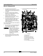
28 Remove the fasteners securing the lower wear
pads and remove the wear pads and
aluminum block between the #1 and #2 boom
tubes.
29 Back the wire cables from the opening below
the #1 boom tube into the tube and then push
them out the end of the #1 boom tube.
Note: This will allow the retract cables to come out
with the boom tubes. Remove the retract wire
cables with the #2 boom tube
30 Begin pulling the #2 boom tube from the
#1 boom tube.
Note: Make sure the tube remains parallel to the
#1 boom tube while removing.
31 When approximately 10 feet of the #2 boom
tube remains in the #1 boom tube, attach a
strap from a suitable overhead lifting device
and slightly lift the tube.
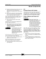
Crushing hazard. The number
2 boom tube may become
unbalanced and fall when it is
removed from the number
1 boom tube if it is not properly
supported and attached to the
overhead crane.
Note: During removal, the overhead crane strap will
need to be adjusted for proper balancing.
32 Remove the final two side wear pads from the
platform end of the machine.
Note: Pay careful attention to the location and
amount of shims used with each wear pad.
33 Support and slide the #2 boom tube from the
boom assembly.
4-3
Primary Boom Lift Cylinder
The primary boom lift cylinder raises and lowers
the primary boom. The primary boom lift cylinder is
equipped with a counterbalance valve to prevent
movement in the event of a hydraulic line failure.
How to Remove the Boom Lift
Cylinder
Bodily injury hazard. This
procedure requires specific repair
skills, lifting equipment and a
suitable workshop. Attempting
this procedure without these skills
and tools could result in death or
serious injury and significant
component damage. Dealer
service is strongly recommended.
Note: When removing a hose assembly or fitting,
the O-ring (if equipped) on the fitting and/or hose
end must be replaced. All connections must be
torqued to specification during installation. Refer to
Specifications,
Hydraulic Hose and Fitting Torque
Specifications.
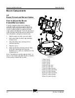
1 Raise the boom until there is approximately
4 feet / 1.2 m between the turntable and boom
rest pad.
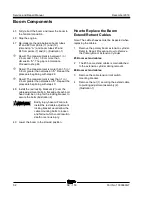
2 Attach a lifting strap from an overhead crane
or other suitable lifting device to the rod end of
the the boom lift cylinder.
Содержание Genie SX-150
Страница 29: ...December 2019 Service and Repair Manual Part No 1300669GT SX 150 17 This page intentionally left blank ...
Страница 105: ...December 2019 Service and Repair Manual Manifolds Part No 1300669GT SX 150 93 ...
Страница 107: ...December 2019 Service and Repair Manual Manifolds Part No 1300669GT SX 150 95 ...
Страница 109: ...December 2019 Service and Repair Manual Manifolds Part No 1300669GT SX 150 97 ...
Страница 115: ...December 2019 Service and Repair Manual Part No 1300669GT SX 150 103 This page intentionally left blank ...
Страница 117: ...December 2019 Service and Repair Manual Part No 1300669GT SX 150 105 ...
Страница 119: ...December 2019 Service and Repair Manual Part No 1300669GT SX 150 107 ...
Страница 122: ...Service and Repair Manual December 2019 Manifolds 110 SX 150 Part No 1300669GT ...
Страница 124: ...Service and Repair Manual December 2019 Manifolds 112 SX 150 Part No 1300669GT ...
Страница 191: ...December 2019 Service and Repair Manual Part No 1300669GT SX 150 179 This page intentionally left blank ...
Страница 229: ...December 2019 Service and Repair Manual 217 Control Circuits Horn ...
Страница 230: ...Service and Repair Manual December 2019 218 SX 150 Part No 1300669GT Control Circuits Horn ...
Страница 231: ...December 2019 Service and Repair Manual Part No 1300669GT SX 150 219 Control Circuits Power ...
Страница 232: ...Service and Repair Manual December 2019 220 Control Circuits Power ...
Страница 233: ...December 2019 Service and Repair Manual 221 Control Circuits Can Bus ...
Страница 234: ...Service and Repair Manual December 2019 222 SX 150 Part No 1300669GT Control Circuits Can Bus ...
Страница 235: ...December 2019 Service and Repair Manual Part No 1300669GT SX 150 223 Control Circuits Deutz TD2011L04i Engine ...
Страница 236: ...Service and Repair Manual December 2019 224 Control Circuits Deutz TD2011L04i Engine ...
Страница 237: ...December 2019 Service and Repair Manual 225 Control Circuits Deutz TD 2 9 L4Engine ...
Страница 238: ...Service and Repair Manual December 2019 226 SX 150 Part No 1300669GT Control Circuits Deutz TD 2 9 L4 Engine ...
Страница 239: ...December 2019 Service and Repair Manual Part No 1300669GT SX 150 227 Control Circuits Perkins 1104D 44T Engine ...
Страница 240: ...Service and Repair Manual December 2019 228 Control Circuits Perkins 1104D 44T Engine ...
Страница 241: ...December 2019 Service and Repair Manual 229 Control Circuits Perkins 854F 34T Engine ...
Страница 242: ...Service and Repair Manual December 2019 230 SX 150 Part No 1300669GT Control Circuits Perkins 854F 34T Engine ...
Страница 243: ...December 2019 Service and Repair Manual Part No 1300669GT SX 150 231 Control Circuits Axle Extend Retract ...
Страница 244: ...Service and Repair Manual December 2019 232 Control Circuits Axle Extend Retract ...
Страница 245: ...December 2019 Service and Repair Manual 233 Control Circuits Steering ...
Страница 246: ...Service and Repair Manual December 2019 234 SX 150 Part No 1300669GT Control Circuits Steering ...
Страница 247: ...December 2019 Service and Repair Manual Part No 1300669GT SX 150 235 Control Circuits Propel ...
Страница 248: ...Service and Repair Manual December 2019 236 Control Circuits Propel ...
Страница 249: ...December 2019 Service and Repair Manual 237 Control Circuits Turntable Rotate ...
Страница 250: ...Service and Repair Manual December 2019 238 SX 150 Part No 1300669GT Control Circuits Turntable Rotate ...
Страница 251: ...December 2019 Service and Repair Manual Part No 1300669GT SX 150 239 Control Circuits Boom Up Down ...
Страница 252: ...Service and Repair Manual December 2019 240 Control Circuits Boom Up Down ...
Страница 253: ...December 2019 Service and Repair Manual 241 Control Circuits Boom Extend Retract ...
Страница 254: ...Service and Repair Manual December 2019 242 SX 150 Part No 1300669GT Control Circuits Boom Extend Retract ...
Страница 256: ...Service and Repair Manual December 2019 244 Control Circuits Jib Up Down Jib Rotate and Platform Rotate ...
Страница 257: ...December 2019 Service and Repair Manual 245 Control Circuits Platform Level and Jib Bellcrank Level ...
Страница 260: ...Service and Repair Manual December 2019 248 Control Circuits Flashing Beacons Oil Cooler and Drive Work Lights ...
Страница 261: ...December 2019 Service and Repair Manual 249 Control Circuits Recovery PLD ...
Страница 262: ...Service and Repair Manual December 2019 250 SX 150 Part No 1300669GT Control Circuits Recovery PLD ...
Страница 263: ...December 2019 Service and Repair Manual Part No 1300669GT SX 150 251 Control Circuits Telematics ...
Страница 264: ...Service and Repair Manual December 2019 252 Control Circuits Telematics ...
Страница 265: ...December 2019 Service and Repair Manual 253 Generator Receptacle Wiring ANSI CSA ...
Страница 266: ...Service and Repair Manual December 2019 254 SX 150 Part No 1300669GT Generator Receptacle Wiring ANSI CSA ...
Страница 267: ...December 2019 Service and Repair Manual Part No 1300669GT SX 150 255 Generator Receptacle Wiring CE ...
Страница 268: ...Service and Repair Manual December 2019 256 Generator Receptacle Wiring CE ...
Страница 269: ...December 2019 Service and Repair Manual 257 Perkins 1104D 44T Engine Electrical Schematic ...
Страница 270: ...Service and Repair Manual December 2019 258 SX 150 Part No 1300669GT Perkins 1104D 44T Engine Electrical Schematic ...
Страница 271: ...December 2019 Service and Repair Manual Part No 1300669GT SX 150 259 Perkins 854F 34T Engine Electrical Schematic ...
Страница 272: ...Service and Repair Manual December 2019 260 Perkins 854F 34T Engine Electrical Schematic ...
Страница 273: ...December 2019 Service and Repair Manual 261 Perkins 854F 34T Engine Harness ...
Страница 274: ...Service and Repair Manual December 2019 262 SX 150 Part No 1300669GT Perkins 854F 34T Engine Harness ...
Страница 275: ...December 2019 Service and Repair Manual Part No 1300669GT SX 150 263 Deutz TD 2 9 L4 Engine Electrical Schematic ...
Страница 276: ...Service and Repair Manual December 2019 264 Deutz TD 2 9 L4 Engine Electrical Schematic ...
Страница 277: ...December 2019 Service and Repair Manual 265 Deutz TD 2 9 L4 Engine Harness ...
Страница 278: ...Service and Repair Manual December 2019 266 SX 150 Part No 1300669GT Deutz TD 2 9 L4 Engine Harness ...
Страница 279: ...December 2019 Service and Repair Manual 267 Hydraulic Schematic ...
Страница 280: ...Service and Repair Manual December 2019 268 Hydraulic Schematic ...
Страница 282: ......

