MLT2 User Manual
23
www.terasic.com
April 12, 2016
4
4
.
.
4
4
D
D
e
e
m
m
o
o
n
n
s
s
t
t
r
r
a
a
t
t
i
i
o
o
n
n
f
f
o
o
r
r
T
T
e
e
r
r
a
a
s
s
i
i
c
c
D
D
E
E
2
2
-
-
1
1
1
1
5
5
F
F
P
P
G
G
A
A
B
B
o
o
a
a
r
r
d
d
This section shows how to setup the painter demo on the Terasic DE2-115 FPGA Board. For other
Terasic FPGA boards, the setup procedures are similar.
H
H
a
a
r
r
d
d
w
w
a
a
r
r
e
e
S
S
e
e
t
t
u
u
p
p
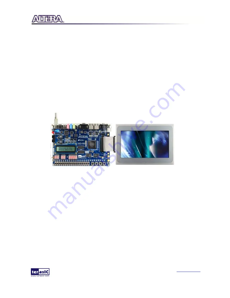
The demonstration configuration is as shown in
F
F
i
i
g
g
u
u
r
r
e
e
4
4
-
-
4
4
.
.
Make sure the ITG adapter is
connected firmly to the IDE cable. Plug the ITG adapter into the GPIO-0 header of the FPGA
development kit from MTL2 before turning on. Important: Plug the MTL2 power adaptor into the
power connector of MTL2 unless the DE2-115 FPGA board is used.
Figure 4-4 DE2-115 ePhoto Configuration Setup
E
E
x
x
e
e
c
c
u
u
t
t
e
e
D
D
e
e
m
m
o
o
n
n
s
s
t
t
r
r
a
a
t
t
i
i
o
o
n
n
Procedure to execute demonstration:
1.
Make sure the DE2-115 is powered off.
2.
Mount the ITG adapter onto the 2x20 GPIO 0 expansion header of the DE2-115.
3.
Connect the DE2-115 USB-Blaster USB port to the PC USB Port with a USB Cable.
4.
Power on the DE2-115 FPGA Development Board.
5.
Make sure Quartus II 13.1 and NIOS II 13.1 are installed in your system.
6.
If you haven’t already, store pictures into the flash memory. For more detailed instructions
please refer to section
4.3 Loading Photos into FLASH
.
7.
Copy the folder Demonstrations\RTL\DE2_115_MTL2_EPHOTO\demo_batch in the MTL2
System CD onto your system and execute “test.bat”.
8.
A photo should be displayed in the LCD, as shown in
F
F
i
i
g
g
u
u
r
r
e
e
4
4
-
-
5
5
.
9.
Slide left or right with one finger on the touch panel to display the previous and next photos
Содержание MTL2
Страница 1: ...p ...


