61
display should show a color picture
Optionally connect a powered speaker to the stereo audio-out jack. Press KEY[1] to hear a 1
kHz humming sound from the audio-out port.
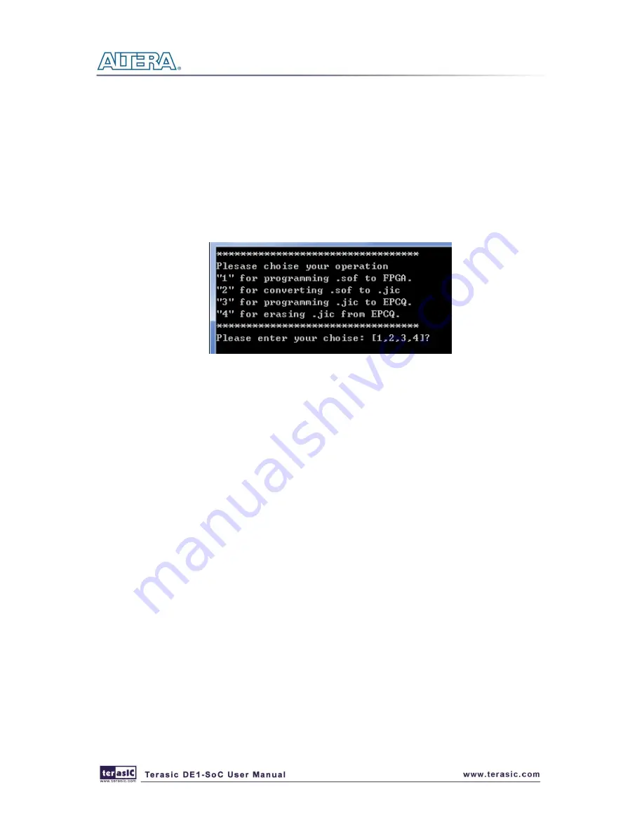
There is a demo_batch folder in the project. It is able to load the bit stream into the FPGA ,
programming or erasing .jic file to EPCQ by executing test.bat file as shown in the
Figure 5-1
.If
user want to download the new design into the EPCQ, the easy method is to copy the new .sof
file into the demo_batch folder and Execute the test.bat. Select the option “2” to covert the .sof
to .jic firstly. Then using the option”3” to program .jic file into EPCQ.
Figure 5-1 Batch file for download FPGA and EPCQ
5
5
.
.
2
2
A
A
u
u
d
d
i
i
o
o
R
R
e
e
c
c
o
o
r
r
d
d
i
i
n
n
g
g
a
a
n
n
d
d
P
P
l
l
a
a
y
y
i
i
n
n
g
g
This demonstration shows how to implement an audio recorder and player using the DE1-SoC
board with the built-in Audio CODEC chip. This demonstration is developed based on Qsys and
Eclipse.
Figure 5-2
shows the man-machine interface of this demonstration. Two push-buttons and
four slide switches are used for users to configure this audio system: SW0 is used to specify
recording source to be Line-in or MIC-In. SW1, SW2, and SW3 are used to specify recording
sample rate as 96K, 48K, 44.1K, 32K, or 8K.
Table 5-1
and
Table 5-2
summarize the usage of
Slide switches for configuring the audio recorder and player.


