Tentative 59001 Скачать руководство пользователя страница 11

SET UP

Turn on the transmitter scroll down and highlight   (Set Up), then press the

STOP ENTER

” button to access Main Set Up screen. 

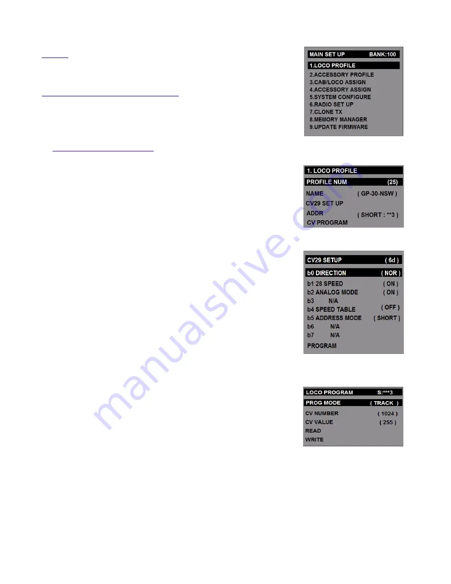
MAIN SET UP: BANK: 100: (SCREEN-1)

All Main setup items are displayed in simple English See each set up items
below.
Scroll ▲ or ▼ to select the desired menu setup title, then Press [STOP] button
on the TX.

1.

LOCO PROFILE: (SCREEN 2)

The locomotive setup data will be stored to this profile number.  It will selected
up to 25 profile numbers. 
Press the [STOP] button to select the desired function below.

1.1)

PROFILE NUM

Press◄ or ► button to select the desired numbers.

1.2)

NAME

Use the keypad to type letters or numbers to name the locomotive. Names
may be 

up to 9 characters long.

1.3)

CV29 SET UP (

SCREEN 3

)

Press the [STOP] button to enter CV29 SET UP: 
The DCC configuration variable CV29 contains very important bits to control
DCC decoder. It must be programmed by complex bit-wise. But you don't need
to calculate the complex bit setting each of the bit position.
Each bit 0 to bit 7 settings of CV29  is shown below.

Bit 0: Loco motor direction( REV or NOR)
Bit 1: 28 speed steps(always ON)
Bit 2: Analog Mode(No DCC decoder equipped locomotive)
Bit 3: Not used
Bit 4: Speed Table: normally off (See the decoder's manual)
Bit 5: DCC address mode: Short or Long 
Bit 6 : Not used 
Bit 7 : Not used

PROGRAM:

Press the [STOP] button and follow the LOCO PROGRAM.  

LOCO PROGRAM MODE: (SCREEN-4)

PROG MODE 

Press [STOP] button to toggle between TRACK or MAIN.

CV NUMBER

Press the number buttons to set the desired DCC CV address number. 

CV VALUE

Press the number buttons to set the desired DCC CV value number.

READ

This function is only active in the TRACK programming mode.
Press [STOP] button, then wait until the reading value displayed one the LCD screen.

(Note: To Read the locomotive  it must be on the programming track)

WRITE

This function allows to send the programming DCC packet to a decoder.


2.4GHz DCC R/C System                                                    

  <

TENTATIVE>

                   11

SCREEN-4

SCREEN-3

SCREEN-2

Содержание 59001

Страница 1: ...SYSTEM INSTALLATION AND OPERATION MANUAL 2 4GHz DCC R C System TENTATIVE 1 Revolution DCC Transmitter TX 59001 DCC 5A Command Booster Station Mobile Receiver 59002 15 AMP Station Command Booster RX 5...

Страница 2: ...contains all the locomotive or accessory DCC data information to connect the DCC decoders Our Transmitter and Receiver are designed to communicate to the DCC decoder in your locomotives or accessories...

Страница 3: ...024 Function and Accessory decoder Decoder address program range Short 2digits 1 127 and Long 4 digits 1 9999 Accessory Address program range 1 2044 Easy access speed steps 28 or 128 Easy access F1 to...

Страница 4: ...DIAGRAM FOR RECEIVER INSTALLATION SET UP 5A DCC RX TRACK POWER MODE DIAGRAM FOR BATTERY INSTALLATION SET UP 2 4GHz DCC R C System TENTATIVE 4 FIG 1 FIG 2...

Страница 5: ...24V DC Key Pad letter Functions T CAB decrease T CAB increase STOP Stop Enter Increase Speed Decrease speed Direction change Direction change Asterisk Quick Program Qiuck menu 0 all stop Function Cont...

Страница 6: ...ow to use the Revolution DCC R C System that need to be understand Refer to the LCD screen menu descriptions for details 2 4GHz DCC R C System TENTATIVE 6 SELECT MODE BANK 35 1 LOCO CONT ROL 2 ACCESSO...

Страница 7: ...d ON three operation menus will be displayed Press button or button to scroll up or down to select the desired menu then press the STOP button to select that function For more information see the corr...

Страница 8: ...he button Then the screen will be changed to the QUICK PROGRAM mode Press the MENU button to exit a ACCELERATION CV3 Press the number buttons between 0 to 255 and then press the STOP button b DECELERA...

Страница 9: ...operating in the LOCO CONTROL mode simply press the button Then the screen view will be changed to the QUICK MENU mode as shown on screen D Press the MENU button to exit a LOCO You can select the loc...

Страница 10: ...turnout switches by single click refer to the ACCESSORY ASSGN SCREEN 15 menu QUICK MENU SCREEN SCREEN F While operating in the ACCESSORY CONTROL mode press the button Then the screen will be changed...

Страница 11: ...ed by complex bit wise But you don t need to calculate the complex bit setting each of the bit position Each bit 0 to bit 7 settings of CV29 is shown below Bit 0 Loco motor direction REV or NOR Bit 1...

Страница 12: ...e the keypad to type numbers to CV value 0 to 255 If the STOP button press the CV value is set in bit wise see the BINARY INPUT Screen 7 READ Press STOP button to read CV value Note The read function...

Страница 13: ...motives Press the UP or DOWN button to select desired L1 to L6 then press or button to select the locomotive profile number How to change the Advanced Consist Address The factory default advanced cons...

Страница 14: ...ct the desired number 4 2 CURRENT CONT Control Current accessory control link intend to setup parameters Press or button to select the desired number 4 3 MULTI LINK MODE Up to 8 turnover switches can...

Страница 15: ...s to the main track Set the DCC MANAGER to ON The default setting is OFF Press button to turn OFF Press button to turn ON 6 RADIO SET UP SCREEN 19 6 1 RADIO SETUP Select the frequency band channel num...

Страница 16: ...memory bank and set to the factory default values Press the STOP button then select YES then press and hold the the STOP button for 1 second Press MENU button to exit 8 4 RESET ALL BANK This function...

Страница 17: ...2 4GHz DCC R C System TENTATIVE 17...

Отзывы: