IB 9006790 (07--2010)
3
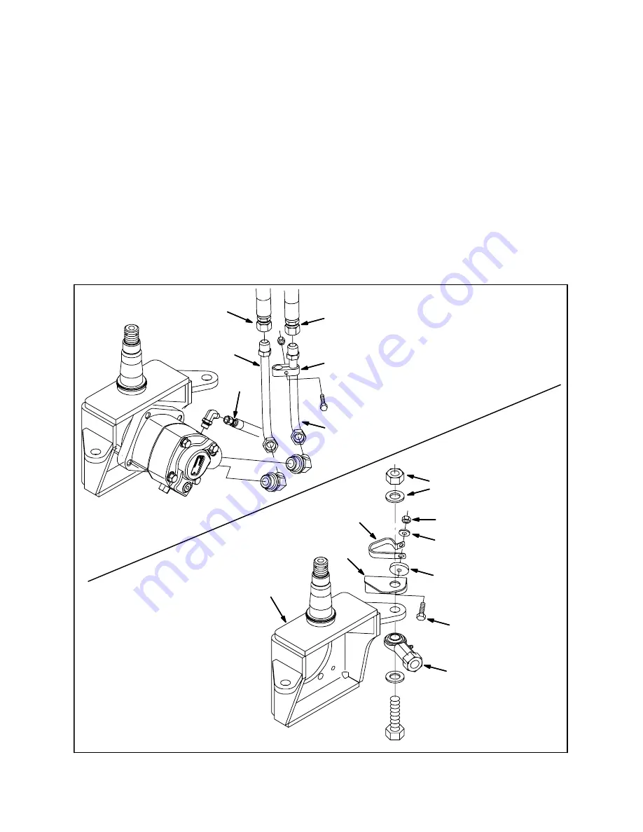
6. Route the 51” hydraulic hose (4) to the right
wheel drive motor and connect the hose to
the motor. Refer to Fig. 4.
7. Install the 2--hole tube clamp onto the
hydraulic tube (2). Refer to Fig. 4.
8. Install the new hydraulic tube (2) onto the
hydraulic motor and connect the hose from
flow divider valve port M3 to the hydraulic
tube. Refer to Fig. 4.
9. Install the hydraulic tube (1) onto the machine
and connect the hose from flow divider valve
port M1 to the hydraulic tube. Refer to Fig. 4.
10. Position the 2--hole tube clamp onto the
hydraulic tube (1) and secure the clamp onto
both tubes. Refer to Fig. 4.
11. Remove the hex nut and washer holding the
hydraulic cylinder assembly to the right drive
support housing, slide the tube support
bracket (5) onto the hex screw, and reinstall
the hex nut and washer. Refer to Fig. 4.
12. Insert the hydraulic hoses attached to the
hydraulic tube (1) and hydraulic tube (2) into
the cable clamp (7). Refer to Fig. 4.
13. Use the hex screw (8), spacer (6), flat washer
(9), and hex nut (10) to install the cable clamp
(7) onto the tube support bracket (5) and
secure the hoses. Refer to Fig. 4.
5
6
7
8
9
10
Remove hex nut and
flat washer to install
tube support bracket
Connected to
hydraulic cylinder
Right drive
support
housing
1
2
2--hole tube clamp
Install hydraulic tube (1)
and hydraulic tube (2)
onto hydraulic motor
Install tube support bracket
(5) onto right drive support
housing
4
Hose from flow
divider valve M3
Hose from flow
divider valve M1
FIG. 4


