background image

PLDC04453

REVISION      00

December 23, 2020

TECHNICAL OFFICE

Stavale

1

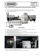
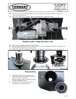
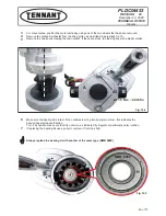
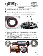
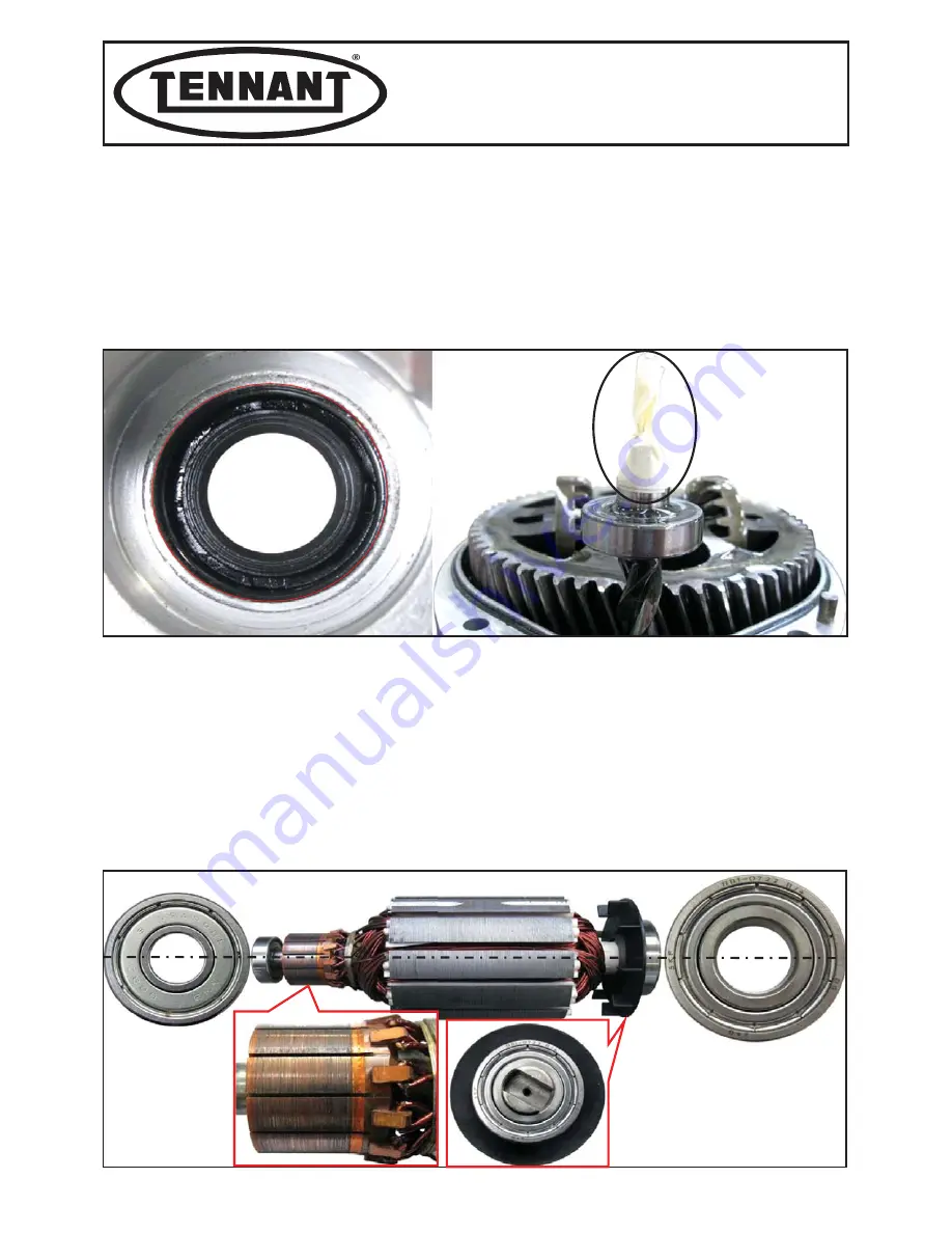
When the oil level has been checked and topped up if necessary, replace the oil seal or gasket 

I

.

2

To remove the oil seal, push it outwards from its seat on the half-housing E.

Make sure that the new oil seal is the same type and size as specified in point 14

3

Fit the oil seal 

I

 on the half-housing 

E, 

pushing it fully into its seat. Use a special ring installer or a

suitable wrench socket, as shown in point 18.

4

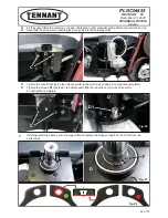
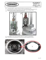
Once having fitted the new oil seal I, before reassembling the half-housing 

E

, wrap adhesive tape or 

rubber-coated paper around the reduction unit-differential shaft, to avoid damaging the oil seal.

5

Apply lubricating grease onto the adhesive tape or rubber-coated paper.

6

Assemble the half-housing 

E

, first inserting the half-axle into the differential, and then the shaft, taking

care not to damage the oil seal.

7

Centre the two reference pins on the other half of the housing, and couple the two halves of the housing
together by hand.

8

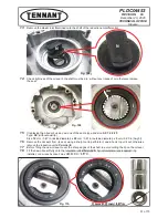
Tighten the four M6 screws 

O

 to a maximum torque of 9.5 Nm  ~ 84 lbf in.

9

Spline the plastic joint 

N

 onto the reduction unit-differential shaft and insert the corrugated washer 

L

.

10

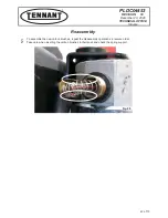
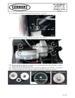
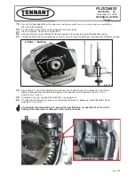
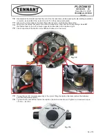
Before assembling the rotor 

C

, check wear of the two bearings 

H

 and 

M

, making sure they are not noisy

or purple in colour, otherwise replace them.

11

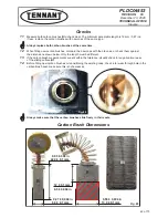
Continue by checking the wear on the rotor switch 

C1

 (where the carbon brushes slide), if dirty, clean by

blowing with compressed air, if slightly damaged clean using an abrasive cloth, while if there is excessive
wear replace the entire rotor 

C

.

Reassembly

*

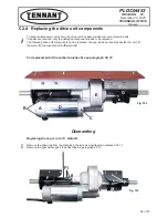
E

I

Fig. 113

M

Fig. 114

H

C

NMB  608Z

BB1 - 0722  B/+

C1

53 of 73

Содержание T390

Страница 1: ...TECHNICAL OFFICE PLDC04453 REVISION DATE December 23 2019 DATE December 23 2020 Stavale T390 TECHNICAL SERVICE MANUAL ...

Страница 2: ......

Страница 3: ...ed in this manual are guaranteed WARNINGS DANGER Indicates the need for attention in order to avoid a series of consequences which could cause death or damage to the health of the operator Indicates particularly important instructions WARNING Indicates the need for attention in order to avoid a series of consequences which could cause damage to the machine or work environment or financial loss i I...

Страница 4: ...egee Checking and replacing the float Tanks Suction Assembly Drive motor Idle wheels B3 C1 Instrument panel board C2 C3 Brush head A2 Replacing the brush motor Checking brush motor current imput Replacing the carbon brushes A1 Relay and drive motor electrical connections Circuit boards Electrical system D3 Wiring diagram D1 E1 Error codes D2 Main Wiring Traction Version Main Wiring Pad Assist ...

Страница 5: ...irty water tank float 29 C DRIVE UNIT C1 INSTRUMENT PANEL ELECTRONIC BOARD 31 C1 1 Instrument panel board setting the type batteries 32 C1 2 Dismantling the instrument panel board 37 C2 DRIVE MOTOR WHEELS 39 C2 1 Checking the drive motor current input 40 C2 2 Checking and replacing the carbon brushes traction motor 41 C2 3 Replacing the complete drive unit motor reduction unit 44 C2 4 Replacing th...

Страница 6: ...ecember 23 2020 TECHNICAL OFFICE Subject Page E ERROR CODES TROUBLESHOOTING E1 ERROR CODES 69 E1 1 Alarm messages on the instrument panel board display 69 E2 TROUBLESHOOTING 71 E2 1 Troubleshooting 71 Information on the revision numbers 73 ...

Страница 7: ...y for the battery versions or unplugging from the mains power supply for the cable versions In this Service Manual the terms RIGHT and LEFT are used to indicate the sides of the machine These always refer to the direction of travel of the machine In this Service Manual the machine version may be written in brackets Traction Pad Assist or quotation marks Traction Pad Assist This note indicates that...

Страница 8: ...PLDC04453 REVISION 00 December 23 2020 TECHNICAL OFFICE Stavale A1 BRUSH MOTOR Fig 1 2 of 73 ...

Страница 9: ...oad i e without brushes 12 Remove the brushes and lower the head using the special pedal control 13 Turn the emergency button clockwise 14 Press the button on the instrument panel to activate the brushes 15 Controlling the rotation of the brushes using the drive lever read the CURRENT A drawn by the brush reduction drive for practicality hold the lever in place with string 16 Note down the value r...

Страница 10: ... 0 A With brushes operating Current input A Amperes Min Max 6 0 A 19 0 A A Disconnect the right motor B Disconnect the black wire from the left motor C Connect the black wire to the right motor D Check the right motor CHECKING THE RIGHT MOTOR A Disconnect the right motor CHECKING THE LEFT MOTOR B Check the left motor Fig 4 Fig 5 4 of 73 ...

Страница 11: ...gency switch to switch off all the functions 4 Lower the brush head using the pedal control 5 Disconnect the batteries from the machine s main wiring 6 Remove the brush head cover unscrewing the four screw 7 Identify the two screw A that secures the metal band on the brush motor 8 Unscrew the screw A and remove the metal band on the brush motor A1 2 Replacing the brush motor carbon brushes Dismant...

Страница 12: ...e figure below The brush must have a minimum length of 8 0 mm 0 315 in 14 Check the sliding contact surface D1 of the carbon brushes I for wear or damage The surface must not be badly worn or burned 15 When fitting new carbon brushes compare the new ones with the old ones or check them against the dimensions given in the figure below Only the length must be different The carbon brushes must all be...

Страница 13: ...n repositioning the metal strap over the carbon brushes D align the notch E in the strap with the corresponding reference on the motor body 19 Arrange the clamp E1 of the metal strap E as shown in the figure below when reassembling 1 Repeat the dismantling operations in reverse 2 To reassemble the carbon brushes perform the dismantling operations in reverse 3 Reposition the protection clamp making...

Страница 14: ...livery control to zero 3 Move the machine onto flat and dry flooring 4 Press the emergency switch 5 Remove the brush motor cover unscrewing the four screws A on the sides 6 Lower the head to simplify the dismantling operations 7 Disconnect the cables B on the motor and the thermal cables C A1 3 Replacing the brush motor Dismantling Fig 13 A A CHEMͲDOSE CONNECTOR B C Fig 14 8 of 73 ...

Страница 15: ...right side 9 Unscrew the metal clamp D from the solution hose E and remove the latter from the distributor 10 Unscrew the 4 bolts F and G that fasten the head checking the positions of the bushings 11 Pull the machine backwards so as to release the head F G E D F F G G Fig 16 Fig 15 9 of 73 ...

Страница 16: ...mantle drive disk disks O 15 Unscrew the bolt P that fastens the drive to the shaft 16 Lift the drive O with the help of a hammer plastic or a puller 17 Pay attention to the tab Q that holds the disk to the shaft 18 Unscrew the seven bolts R on each motor that fasten the reduction drive to the head plate 19 Replace the reduction drive with a new one O P Q R O Fig 18 Q Fig 17 Fig 19 10 of 73 ...

Страница 17: ... lock tighten to a maximum torque of 25 5 Nm 225 7 lbf in 3 Respect the positioning of the reduction drives on the brush head plate see Figure 20 Check the direction of rotation of the brushes see Figure 46 the right brush must rotate anticlockwise and the left brush clockwise If this is not the case reverse the electrical cables to the motor that is rotating in the wrong direction paying special ...

Страница 18: ...ine s electronics by simply disconnecting the negative pole only for the battery versions or unplugging from the mains power supply for the cable versions In this Service Manual the terms RIGHT and LEFT are used to indicate the sides of the machine These always refer to the direction of travel of the machine In this Service Manual the machine version may be written in brackets Traction Pad Assist ...

Страница 19: ...PLDC04453 REVISION 00 December 23 2020 TECHNICAL OFFICE Stavale SUCTION MOTOR B1 Fig 21 13 of 73 ...

Страница 20: ...DC 10 Turn the ignition key on the mushroom shaped switch clockwise to connect power 11 Start the suction motor by pressing the corresponding button on the instrument panel 12 Read the CURRENT A drawn by the suction motor 13 Compare the values measured against the chart below 14 If all the values are normal close the top dirty water tank again 15 If the measurements do not correspond to those spec...

Страница 21: ...Lift and turn the top dirty water tank 4 Isolate and disconnect the power connector A to the suction motor see Figure 19 5 Remove the top cap B on the suction motor this operation can be performed without removing the air exhaust pipe 6 To remove the cap B pull the metal catch C outwards and open the two tabs D B1 2 Replacing the suction motor carbon brushes B C D Fig 26 Fig 25 A 15 of 73 ...

Страница 22: ...bon brush support F and remove the motor carbon brush G 10 Measure the carbon brush if the length is between 23 7 mm 0 93 in maximum and 5 0 1 mm 0 2 0 04 in minimal the carbon brush is still working otherwise it must be replaced 11 Repeat the operation for the second carbon brush 1 Replace the suction motor performing the dismantling operations in reverse 2 Test the correct operation of the sucti...

Страница 23: ...move the white plastic clamp B that fastens the cable to the suction motor plate 6 Unscrew the two M6 screw C that fasten the suction unit motor to the dirty water tank 7 Remove the suction motor from its compartment 8 Check that the area inside the circle and the suction motor gasket D are not moist or wet a sign of liquid being drawn in that may damage the bearings inside the suction motor causi...

Страница 24: ...sorbing sponge G suction motor air exhaust pipe When replacing the motor also replace the suction motor gasket D purchased separately 10 Replace the motor and assemble it as shown in Figures 25 26 1 For assembly perform the dismantling operations in reverse 2 Test the correct operation of the suction motor see paragraph B 1 1 Reassembly D E F G Fig 31 Fig 32 G G G F F F G 18 of 73 ...

Страница 25: ...PLDC04453 REVISION 00 December 23 2020 TECHNICAL OFFICE Stavale B2 SQUEEGEE UNIT Fig 33 19 of 73 ...

Страница 26: ...even contact with the floor with suitable deflection across the width Figure 28 6 If this is not the case adjust the blade 7 First adjust the angle of the squeegee using the bolt A until the blade touches the flooring uniformly 8 Adjust the deflection of the squeegee blade using the two wheels B tightening decreases the deflection loosening increases the deflection Adjust until one edge of the bla...

Страница 27: ... the squeegee taking deflection off the centre 10 Unscrewing the bolt A the squeegee support rais the edges of the squeegee decreasing the deflection on the blade at the sides of the squeegee and it increasing deflection on the centre 11 Once having found the right angle when the squeegee is perfectly parallel to the flooring hold screw A in place lock the position with the nut C C C Fig 35 Fig 36...

Страница 28: ...g the screw D the squeegee rises decreasing the deflection on the blade 14 By unscrewing screw D the squeegee is lowered increasing the deflection on the blade 15 Once having found the right deflection when the blades are slanted correctly with respect to the floor hold screw D in place lock the position with the nut E Fig 37 D E 22 of 73 ...
Страница 29: ... symmetrically so that they can be rotated on all four edges before being replaced see Fig 33 The rear squeegee blade should be turned around every 50 operating hours 1 Clean the squeegee blades before reassembling them 2 Clean the body of the squeegee where the old or new blades will be fitted 3 Arrange the blades on the squeegee lining up the holes with the reference pins E do not exchange the f...

Страница 30: ...e blade pressing devices front and rear 6 Reposition the squeegee on the support and reassemble the suction hose 7 Adjust the squeegee as described in paragraph B 2 1 1 For the complete replacement of the squeegee proceed as described in points B 2 1 2 For the replacement of the squeegee body only proceed as described in points B 2 1 and B 2 2 B2 3 Replacing the squeegee Fig 42 H Fig 43 24 of 73 ...
Страница 31: ...PLDC04453 REVISION 00 December 23 2020 TECHNICAL OFFICE Stavale B3 CHECKING AND REPLACING THE FLOATS Fig 44 OFF CLIC ON 25 of 73 ...
Страница 32: ...6 Lift the dirty water tank to access the connector A on the float 7 Unplug the connector A so as to be able to perform the check 8 Connect the two tester probes to the pins on the float connector the position is not important 9 If the float is working correctly the tester will emit a BEEP if featured or will display a value with just zeroes 10 Plug the connector back in 11 If the tester display d...

Страница 33: ... unscrewing the bolt C 8 Remove the float from the solution tank 9 Replace the float with a new one D 1 Fit the new float performing the dismantling operations in reverse 2 Pay special attention to the position of the float in the tank see Figure 45 3 Pay special attention to the seal gasket E on the new float 4 Tighten the float to the tank holding the body B and tightening the bolt C making sure...

Страница 34: ...tion tank 7 Identify the float connector B 8 Unplug the connector B so as to be able to perform the check 9 Connect the two tester probes to the pins on the float connector the position is not important 10 Keep the float raised by hand or hold it position with an elastic band see Figure 49 11 If the float is working correctly the tester will emit a BEEP if featured or will display a value with jus...

Страница 35: ...side the tank 8 Remove the float from the tank holding the body of the float E and unscrewing the bolt F 8 Remove the float from the dirty water tank 9 Replace the float with a new one E 1 Fit the new float performing the dismantling operations in reverse 2 Position the float as shown in Figure 57 with the part G tilted towards the bottom of the tank 3 Pay special attention to the seal gasket H on...

Страница 36: ...hine s electronics by simply disconnecting the negative pole only for the battery versions or unplugging from the mains power supply for the cable versions In this Service Manual the terms RIGHT and LEFT are used to indicate the sides of the machine These always refer to the direction of travel of the machine In this Service Manual the machine version may be written in brackets Traction Pad Assist...

Страница 37: ...ION 00 December 23 2020 TECHNICAL OFFICE Stavale On the Traction version the board also comprises the circuits that deliver power the drive motor C1 INSTRUMENT PANEL ELECTRONIC BOARD i TRACTION VERSION Fig 66 31 of 73 ...

Страница 38: ... affect battery life and operating autonomy The type of battery is marked on the battery casing The batteries can be divided into three categories Pb Acd lead acid AGM locked acid and GEL with the plates coated by gel 1 Turn the ignition key A1 on the emergency button A to the right 2 Press and hold the brush button B and the suction motor button C together for around 5 seconds and in any case unt...

Страница 39: ...the type of batteries or the water solution metering mode Water solution is indicated as the clean water tank can be filled with either a solution of water and detergent or water only using the special Chem dose kit that distributes the detergent to be mixed with water directly onto the brushes thus avoiding waste i Setting EcoMode on Traction versions with drive C C Fig 69 B B Fig 70 33 of 73 ...

Страница 40: ...red 6 To save the settings simply switch the machine off using the emergency button A for machines with drive For all other machines press and hold the brush button B until the display switches off i A Fig 72 EcoMode on models with electric drive delivers a flow of solution that is proportional to machine travel speed as is already currently available on our large rideͲon machines 6 20 12Ͳ40 18 60...

Страница 41: ... Press and hold the brush button B and the suction motor button C together for around 5 seconds and in any case until the display shows the type of batteries set 9 Use the button C to select the type of battery between GEL and ACID Setting on Pad Assist versions without drive B Fig 73 C B Fig 74 C C Fig 75 35 of 73 ...

Страница 42: ...press the brush button B and the suction motor button C together for 5 seconds or wait around 10 seconds until the display shows the machine operating hours 11 Switch the machine off by pressing the brush on off button for more than 3 seconds 10 sec Fig 77 C C B B B C Fig 76 Fig 78 B 36 of 73 ...

Страница 43: ...wer the machine to avoid dangerous short circuits 3 Unscrew the three screws B that fasten the instrument panel to the dirty water tank 4 Lift the board and turn it over with care 5 Disconnect the multi wire orientation sensitive connectorsC D from the electronic board with care C1 2 Dismantling the instrument panel board Disassembly Fig 79 B B A Fig 80 C D 37 of 73 ...

Страница 44: ...t important 7 Detach the two wires orange and purple connected to the forwards reverse switch F when reassembling being an ON OFF contact the position of the wires is not important 8 Disconnect the four pin connector G dedicated to traction motor taking special care Assembly is orientation sensitive by the locking connector fitted on the instrument panel board 1 To assemble the new instrument pane...

Страница 45: ... The wheel axle speed increases to 150 rpm the gear ratio between electric motor shaft and wheel axle speed is 21 1 while ingress protection against solids and liquids is IP44 The electric motor power wires are fitted with a ferrite so as to comply with the new European standards on electromagnetic compatibility The lubricant used inside the reduction drive is ISO 150 PAO oil a synthetic polyalpha...

Страница 46: ... key on the emergency switch clockwise 13 Turn the speed controller on the instrument panel completely clockwise see Figure 340 14 Select forwards gear using the button on the instrument panel and press the enable brush lever 15 Read the CURRENT with the motor at no load without the machine operating 16 Lower the wheels back to the ground and read the CURRENT with the machine in drive with the tan...

Страница 47: ...ency key switch until it is held in the bottom position 4 Remove the squeegee from the mount 5 Disconnect the batteries from the wiring and each other and remove them from the battery compartment 6 Tilt the machine over until it rests on the left side 7 It is recommended to lay something soft between the floor and the side to avoid damaging the side 8 Identify the two caps A holding the carbon bru...

Страница 48: ...e dimensions shown below Only the length must be different 13 If the carbon brush measurements are still within the tolerance visually check for any abnormal wear of the sliding surface B1 14 Before fitting new carbon brushes or repositioning the existing ones check rotor wear through hole in the carbon brush seat make sure this is not excessive Always make sure that the carbon brushes slide freel...

Страница 49: ... 2020 TECHNICAL OFFICE Stavale 1 To assemble the new carbon brushes repeat the disassembly operations in reverse order 2 Take care when inserting the carbon brushes in their seat and check the spring support Reassembly Fig 90 43 of 73 ...

Страница 50: ...sconnect the batteries from the wiring and each other and remove them from the battery compartment 6 Tilt the machine over until it rests on the left side 7 It is recommended to lay something soft between the floor and the side to avoid damaging the side 8 Unscrew the two screws and remove the two drive wheels from the drive motor axle 9 Electrically disconnect the drive motor both the thermal cut...

Страница 51: ...right one D fastened by the two screws D1 and the left one E fastened by the three screws E1 14 Replace the drive motor with a new one and then reassemble the half supports on the reduction unit 1 Fit the left support E on the reduction unit tightening the three screws E1 to a maximum torque of 22 Nm 194 7 lbf in Place the Seeger rings F on the shaft making sure they are fitted correctly 2 If poss...

Страница 52: ...aft into the half support D 5 Tighten the nuts C that fasten the half support E to the machine s chassis do not tighten completely 6 Tighten the screws D1 that fasten the half support D to the reduction unit on the drive motor do not tighten completely 7 correct side Carefully insert the bearing onto the support D and replace the Seeger rings F on the shaft from the Fig 95 D C Fig 96 E C D D1 Fig ...

Страница 53: ...onnection to the drive motor performing the dismantling operations in reverse making sure the connections are correct 11 Replace the wheels tightening the screws to a maximum tightening torque of 23 Nm 203 6 lbf in 12 Complete the assembly of the machine repeating the dismantling operations in reverse 23 Nm 203 6 lbf in Fig 100 23 Nm 203 6 lbf in 23 Nm 203 6 lbf in Fig 101 9 5 Nm 84 1 lbf in Fig 9...

Страница 54: ...ents can be replaced the cap A the carbon brushes B the rotor C the stator D the reduction unit differential E For replacement of the carbon brushes B see paragraph C2 10 Replacing the cap A rotor C stator D 1 Remove the drive unit from the machine s chassis as described in paragraph C2 11 2 Remove the right half support F as described in paragraph C2 11 C2 4 Replacing the drive unit components i ...

Страница 55: ...hese are stuck tap them lightly with a plastic mallet 6 Make sure the bearing H is intact if the outside steel ring turns purple in colour this indicates the bearing has started overheating Turn it by hand to make sure that it is not worn as indicated by irregular or particularly noisy rotation 7 If replacing the bearing H use a puller to remove it from the shaft Always replace the bearing H with ...

Страница 56: ... the same time remove the stator D removing it from the studs If necessary to assist removal tap it with a plastic mallet 10 Then remove the rotor C by pulling it upwards vertically 11 Check tightness of the oil seal or gasket I fitted on the reduction unit differential E 12 Check that the corrugated washer L is on the bearing support base M and remove it I Fig 107 L L N D E E C C 1 2 Fig 106 50 o...

Страница 57: ... 12 mm 0 47 in inside diameter x 22 mm 0 87 in outside diameter x 5 mm 0 20 in height 16 Remove the oil seal I from its seat using a sharp tool to perforate it and a hook to pull it out otherwise remove the reduction unit differential E 17 Before fitting the new oil seal cover the sharp edges of the shaft to avoid cutting the lip on the oil seal 18 Fit the new oil seal I fully onto the reduction u...

Страница 58: ...e with planetary gearing 24 Use callipers to check the height of the oil level in the reduction unit The oil level is correct if the distance between the oil level and the edge of the reduction unit is between 12 5 mm 0 5 in and 13 0 mm 0 52 in 25 If needing to top up use AGIP BLASIA 150 or equivalent oil 26 If on the other hand need to change or completely refill with oil always use AGIP BLASIA 1...

Страница 59: ... or rubber coated paper 6 Assemble the half housing E first inserting the half axle into the differential and then the shaft taking care not to damage the oil seal 7 Centre the two reference pins on the other half of the housing and couple the two halves of the housing together by hand 8 Tighten the four M6 screws O to a maximum torque of 9 5 Nm 84 lbf in 9 Spline the plastic joint N onto the redu...

Страница 60: ...cables that power the carbon brushes B are intact and the corresponding screws B1 that fasten them to the carbon brush supports and the latter to the cap A are tight 15 Check operation of the thermal cutout B2 and make sure it is secure 15 If everything is OK complete assembly of the motor fitting the cap A otherwise resolve the problems and then complete assembly 16 Tighten the two nuts A1 that f...

Страница 61: ...emble as illustrated in the previous points 22 Tighten the screws P to a maximum torque of 22 Nm 194 7 lbf in 23 The drive unit is now ready to be fitted on the machine however first check its electrical operation as described in Testing 24 To assemble the drive unit on the machine s chassis see the instructions in the previous paragraph 1 If replacing or dismantling the electrical parts of the dr...

Страница 62: ...n tap the end of the spanner lightly yet firmly with a hammer 9 Make sure not to lose the Grover washer B located behind the flat wide washer 10 Remove the old wheel if necessary use a rubber mallet 11 Position the tab E in place on the shaft if necessary to fit the new wheel 12 Fit the new wheel and push it in fully using a rubber mallet 1 Check that the Seeger ring C is intact and check the posi...

Страница 63: ...rear on the right near the solenoid valve 5 Disconnect the brown wire A and the black wire B and join them together using a piece of wire 6 Check if the relay is working correctly 6a If the machine moves check if there is voltage 24V at the wires C and D 6b If the machine moves and there is voltage at the wires C and D replace the relay 6c If the machine does not move check if there is power suppl...

Страница 64: ... wiring and each other and remove them from the battery compartment 5 Remove the bettery plate 6 Identify the crosshead screw closest to the relay 7 Unscrew the screw and proceed to replace the relay 8 Proceed with the electrical connection shown below 1 To assemble the new relay complete the dismantling operations in reverse 2 Pay attention to the connection to the relay the other connections are...

Страница 65: ...hine s electronics by simply disconnecting the negative pole only for the battery versions or unplugging from the mains power supply for the cable versions In this Service Manual the terms RIGHT and LEFT are used to indicate the sides of the machine These always refer to the direction of travel of the machine In this Service Manual the machine version may be written in brackets Traction Pad Assist...

Страница 66: ... eliminating the interconnection wires The board includes the 2 A fuse for the functions the board and the solenoid valve The 30A drive fuse The 40A suction motor fuse and 50A brush motor fuse There are some variants to the wiring such as the cable to power the current reading board used for the rollers the wiring to power the Chem dose pump if featured and the connector to assemble the on board b...

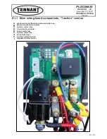
Страница 67: ...solenoid valve fuse B Main wiring board connector C Suction motor relay D Contactor brush motor E Brush motor fuse F Suction motor fuse G Drive motor fuse H Positive isolator switch I Negative isolator switch D1 1 Main wiring board components Traction version C I H G F E D B A Fig 127 61 of 73 ...

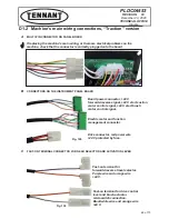
Страница 68: ...the machine check that the connector is correctly plugged onto the board Board power connector 24 V forwards reverse signal 24 V start suction motor control signal 24 V start brush motor control signal Electric motor and function management connector Drive connector red power wire 24 V protected by fuse Fast on terminal for forwards reverse travel selector Purple wire and orange wire 24 V Fast on ...

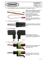
Страница 69: ... lugs roller version only powers the current reading board Orange wire with spade lugs to connect to the mushroom head button with key carries 24 V signal to the functions Fig 131 Suction motor connector red wire 24 V protected by fuse and blue negative wire Fig 132 Battery terminals and terminal covers Red wire on the positive pole black wire on the negative pole Fig 133 Sealed connector for dirt...

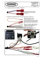
Страница 70: ...V Fig 135 Drive motor connection Fast on terminal brown wire and fast in terminal grey wire Relay coil connector fast on terminal black wire connected directly to the negative isolator switch 0 V Drive motor protector connector Male tubular cable lugs for red wire female tubular cable lugs for orange wire 24 V Relay coil connector fast on terminal orange wire 24 V Fig 136 24V 24V 24V 24V 24V 24V 2...

Страница 71: ...he negative isolator switch Fig 138 Brush motor protector fast on terminal connector Yellow black wire and brown white wire 0 V Fig 139 Connect the red wire to the motor s positive pole and the black wire to the negative The thermal protector has orientation sensitive connectors Fig 140 Two pin connector for connecting the Chem dose pump Pink wire 24 V yellow black wire 0 V in series with the brus...

Страница 72: ...us preventing machine operation The sealed connector provided for the on board battery charger must be detached from the microswitch and connected to the microswitch on the battery charger Fig 142 Connection via Ø 8 mm cable eyelet Only used on machines with roller head not used on the others Red wire 24 V coming directly from the positive isolator switch Connected directly to ground on the brush ...

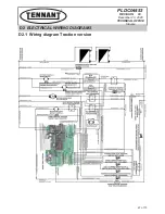
Страница 73: ...PLDC04453 REVISION 00 December 23 2020 TECHNICAL OFFICE Stavale D2 1 Wiring diagram Traction version D2 ELECTRICAL WIRING DIAGRAMS 67 of 73 ...

Страница 74: ...ectronics by simply disconnecting the negative pole only for the battery versions or unplugging from the mains power supply for the cable versions In this Service Manual the terms RIGHT and LEFT are used to indicate the sides of the machine These always refer to the direction of travel of the machine In this Service Manual the machine version may be written in brackets Traction Pad Assist or quota...

Страница 75: ... turning the key for around 2 seconds all the LEDs and the display will switch on Immediately after this the display will be show in sequence the firmware loaded on the electronic board F05 Firmware 05 the hardware version of the instrument panel board r01 Release 01 type of electronic board o09 Option 09 and finally total machine operating hours which remain displayed until the machine is shut do...

Страница 76: ...mal protector to cool down Check drive motor current draw Replace the instrument panel board Drive shutdown due to low battery voltage Replace the instrument panel board BLT DRIVE LEVER already pressed when starting or after emergency Electronic board MOSFET short circuited Drive motor protector activated HOT Check that the drive motor cable is not interrupted Replace the instrument panel board AC...

Страница 77: ...to the wiring diagram 1 2 Replace the brush motor Check the brush motor If the motor is intact go to point 10 If there is continuity go to point 9 3 Replace the squeegee If the squeegee is clean and intact go to point 4 Check that the suction hose is clean and intact B 3 2 B 3 4 4 Otherwise restore continuity Otherwise replace it Check the lid gasket see paragraph B 5 1 4 Check that the squeegee b...

Страница 78: ... is a voltage of 24 V at the ends of the solenoid valve wires Check the connections under the instrument panel see paragraph C 4 2 C 4 3 1 Check the error codes on the instrument panel board display see chapter E 1 1 E2 1 6 The machine doesn t move forwards Replace the instrument panel board see paragraph C 4 2 C 4 3 If the output voltage is not 24 V check the wiring replace the instrument panel b...

Страница 79: ...PLDC04453 REVISION 00 December 23 2020 TECHNICAL OFFICE Stavale REVISION No DATE REVISION 00 Drafting of the manual and release date REVISION 01 December 23 2020 73 of 73 ...

Отзывы: