TROUBLE SHOOTING GUIDE
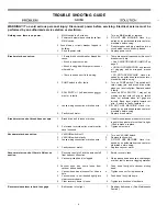
Prespray wand does not spray.
1.
MAIN and PUMP switches are off.
2.
Trigger is locked on wand.
3.
Spray jet on wand is plugged.
4.
Solution screen is plugged and has shut
off flow of water to solution pump.
5.
Loose or broken wiring.
6.
Faulty MAIN switch.
7.
Faulty solution pump.
1.
Turn on MAIN and PUMP switches.
2. Unlock trigger.
3.
Remove spray jet and clean it with an
browning chemical.
4.
See ONCE EACH MONTH.
5.
DO NOT USE MACHINE. Have it re-
paired by an authorized service center or
electrician before using.
6.
Replace MAIN switch.
7.
Replace solution pump.
No spray through spray jets.
1.
MAIN switch is off.
1.
2.
PUMP switch is off.
2.
3.
User is not twisting rolling control grips.
3.
4.
Solution screen is plugged and has shut
off flow of water to solution pump.
4.
See ONCE EACH MONTH.
5.
Spray jets are plugged.
5.
6.
Loose or broken wiring.
6.
7.
Faulty solenoid valve.
8.
Faulty MAIN or PUMP switch.
9.
ROLL SWITCH 1 needs adjustment or is
faulty. Drive motor will not run in this
situation.
10. Faulty solution pump.
10.
Replace solution pump.
7.
8.
9.
Turn MAIN switch on.
Turn PUMP switch on.
Twist roll grips forward. This starts spray,
brush motor and drive motor.
See ONCE EACH MONTH.
DO NOT USE THE MACHINE. Have it
repaired by an authorized service center
or electrician before using.
Replace solenoid valve.
Replace faulty switch.
Lever on ROLL SWITCH 1 may not be
making contact with roll grip, so switch
does not activate when roll grips are
turned. Bend lever slightly toward roll
grip. If switch is faulty, replace it.
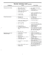
Extractor does not move when
rotating control grips.
1.
Reverse release lever is engaged.
1.
2.
Drive belt is loose.
2.
3.
Drive belt is worn.
3.
4.
5.
6.
7.
8.
9.
10.
11.
Drive belt is wet.
MAIN switch is off.
SPEED CONTROL knob is turned to
slowest setting.
2.5 amp circuit breaker tripped.
Loose or broken wiring.
ROLL SWITCH 1 or 2 needs adjustment
or is faulty.
SPEED CONTROL BOARD needs ad-
justing or is faulty.
Faulty drive motor.
4.
5.
6.
7.
8.
9.
10.
11.
Disengage reverse release lever.
Tighten belt. (See Maintenance Section.)
Replace drive belt. (See Maintenance
Section.)
Dry belt off.
Turn MAIN switch on.
Turn SPEED CONTROL knob on dash to
desired speed setting.
Push breaker button to reset.
DO NOT USE MACHINE. Have it re-
paired by an authorized service center or
electrician before using.
Lever on either of two switches may not be
making contact with roll grip, so switch
does not activate when roll grips are
turned. Bend levers slightly toward roll
grip. If a switch is faulty, replace it.
See your authorized service center for
proper adjustment or replacement.
Replace drive motor.
A - -
7
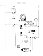
Содержание castex falcon 2800 WF2800
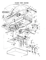
Страница 12: ...CHASSIS PARTS DIAGRAM I 54 45 44 1 y 1 93 28 83 J 103 4 104 F 105 I 106...
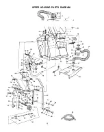
Страница 14: ...UPPER HOUSING PARTS DIAGRAM 3 J7 U J 8 e12 15 I I i 7 332 27 i 65...
Страница 20: ......

