background image

OPERATION

23

800D MM308 (3–95)

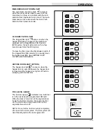
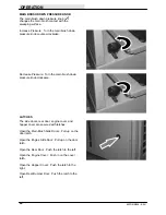
FILTER SHAKER SWITCH

The filter shaker switch 

 starts the hopper

dust filter shaker. The shaker automatically
operates for 40 seconds.

Start:  Press the filter shaker switch. The indicator
light will remain on while the filter shaker is
operating.

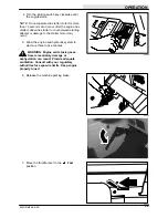
Stop:  Press the filter shaker switch again IF
wanting to stop the filter shaker during the 40
second shaking cycle.

NOTE: The vacuum fan shuts off while the filter
shaker is operating.

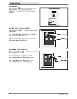
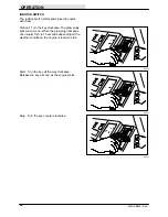
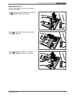
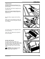
VACUUM FAN SWITCH

The vacuum fan switch 

 starts and stops the

vacuum fan.

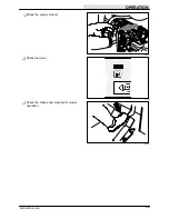
Start:  Press the vacuum fan switch. The indicator
light above the switch will come on.

Stop:  Press the vacuum fan switch. The indicator
light above the switch will go off.

08229

08231

Содержание 800D

Страница 1: ...800D MM308 Operator Manual ...

Страница 2: ...servicing it This machine will provide excellent service However the best results will be obtained at minimum costs if The machine is operated with reasonable care The machine is maintained regularly per the maintenance instructions provided The machine is maintained with TENNANT supplied or equivalent parts Manual Number MM308 Revision 07 Published 11 95 Copyright 1993 1994 1995 TENNANT Printed i...

Страница 3: ...ION 21 FUEL LEVEL GAUGE 21 HOURMETER 22 HAZARD LIGHT SWITCH OPTION 22 OPERATING LIGHTS SWITCH 22 FILTER SHAKER SWITCH 23 VACUUM FAN SWITCH 23 IGNITION SWITCH 24 Page MAIN BRUSH SWITCH 25 STEERING WHEEL 26 STEERING WHEEL TILT LEVER 26 BLOWER WAND LEVER OPTION 26 CIRCUIT BREAKERS 27 GLOW PLUGS LIGHT 27 MAIN BRUSH DOWN PRESSURE KNOB 28 LATCHES 28 OPERATOR SEAT 29 HOPPER SUPPORT BAR 29 WINDSHIELD WIPE...

Страница 4: ...RAG CHAIN 70 DEBRIS HOPPER 71 HOPPER DUST FILTER 71 TO REMOVE OR REPLACE HOPPER DUST FILTER 71 THERMO SENTRY 73 Page BRUSHES 73 MAIN BRUSH 73 TO REPLACE MAIN BRUSH 73 TO CHECK AND ADJUST MAIN BRUSH PATTERN 74 SIDE BRUSH 77 TO REPLACE SIDE BRUSH 77 SKIRTS AND SEALS 78 HOPPER LIP SKIRTS 78 BRUSH COMPARTMENT SKIRTS 78 REAR SKIRTS 79 BRUSH DOOR SEALS 79 HOPPER SEALS 79 HOPPER DOOR SEALS 79 HOPPER SIDE...

Страница 5: ...slow on inclines and slippery surfaces use care when reversing machine move machine with care when hopper is raised make sure adequate clearance is available before raising hopper do not carry passengers on machine always follow safety and traffic rules report machine damage or faulty operation immediately 5 Before leaving or servicing machine stop on level surface set parking brake turn off machi...

Страница 6: ...T ARMS LABEL LOCATED ON BOTH HOPPER LIFT ARMS HOPPER SUPPORT BAR LABEL LOCATED ON THE HOPPER LIFT ARMS CROSS TUBE AND ON BOTH HOPPER LIFT ARMS NOISE LABEL LOCATED ON THE FRONT PANEL OF THE OPERATOR COMPARTMENT EMISSIONS LABEL LOCATED ON THE FRONT PANEL OF THE OPERATOR COMPARTMENT 07623 FOR SAFETY LABEL LOCATED ON THE FRONT PANEL OF THE OPERATOR COMPARTMENT ENGINE FAN AND BELT LABEL LOCATED ON THE ...

Страница 7: ...pervisor when the required maintenance intervals occur as stated in the MAINTENANCE section of this manual Read this manual carefully before operating this machine FOR SAFETY Do not operate machine unless operation manual is read and understood Check the machine for shipping damage Check to make sure machine is complete per shipping instructions Check the hydraulic fluid level in the hydraulic res...

Страница 8: ...fuel system service area Keep area well ventilated After the first 50 hours of operation follow the recommended procedures stated in the MAINTENANCE CHART Keep your machine regularly maintained by following the maintenance information in this manual We recommend taking advantage of a regularly scheduled service contract from your TENNANT representative Order parts and supplies directly from your a...

Страница 9: ... 800D MM308 1 93 MACHINE COMPONENTS A B C D E F G H I 07623 A Operator Seat F Hopper Cover B Steering Wheel G Side Brush C Engine Cover H Instrument Panel D Engine Side Door I Hopper Door E Main Brush Access Door ...

Страница 10: ...Light Hopper Temperature Thermo Sentry Side Brush Down Pressure Heavy Main Brush Shut Down Side Brush Down and On Filter Clogged Side Brush Up and Off Hopper Door Closed Hopper Door Close Fuel Hopper Door Open Hourmeter Hopper Roll In Hazard Light Hopper Roll Out Operating Lights Hopper Down Fan Hopper Up Steering Wheel Tilt Horn Main Brush Down and II Speed Charging System Main Brush Off ...

Страница 11: ...ed Circuit Breaker 5 Main Brush Down Pressure Light Circuit Breaker 6 Main Brush Down Pressure Heavy Circuit Breaker 7 Circuit Breaker 1 Circuit Breaker 8 Circuit Breaker 2 Circuit Breaker 9 Circuit Breaker 3 Parking Brake Circuit Breaker 4 Glow Plugs Preheat ...

Страница 12: ...Lever T Hazard Light Switch Option F Side Brush Down Pressure Knob U Operating Light Switch G Hopper Door Lever V Filter Shaker Switch H Hopper Rollout Lever W Vacuum Fan Switch I Hopper Lift Lever X Ignition Switch J Horn Button Y Main Brush Switch K Charging System Light Z Steering Wheel L Engine Oil Pressure Light AA Steering Column Tilt Lever M Engine Water Temperature Light BB Circuit Breaker...

Страница 13: ...ge the speed of the machine with the pressure of your foot the harder you press the faster the machine travels Forward Press the top of the directional pedal with the toe of your foot Reverse Press the bottom of the directional pedal with the heel of your foot Neutral Take your foot off the directional pedal and it will return to the neutral position 08467 08468 08469 ...

Страница 14: ...p Take your foot off the directional pedal and let it return to the neutral position Step on the brake pedal PARKING BRAKE For machines below serial number 001103 The parking brake pedal sets and the lever releases the front wheel brakes Set Step on the parking brake pedal FOR SAFETY Before leaving or servicing machine stop on level surface set parking brake turn off machine and remove key Release...

Страница 15: ...103 and above The parking brake lever sets and releases the front wheel brakes Set Pull the parking brake lever up FOR SAFETY Before leaving or servicing machine stop on level surface set parking brake turn off machine and remove key Release Push the parking brake lever down ...

Страница 16: ...OPERATION 800D MM308 6 94 14 THROTTLE LEVER The throttle lever controls the engine speed Fast Pull the lever into the Fast position Idle Push the lever into the Idle position 08456 08457 ...

Страница 17: ...ll the side brush position lever back and to the left into the Off Up slot SIDE BRUSH SWITCH For machines serial number 001177 and above The right side brush switch controls the right side brush position and rotation The optional left side brush switch controls the optional left side brush position and rotation Down and On Press the top of the switch into the On Down position Up and Off Press the ...

Страница 18: ... For machines below serial number 001177 Heavy Turn the side brush down pressure knob counter clockwise Light Turn the side brush down pressure knob clockwise For machines serial number 001177 and above Increase Pressure Turn the side brush down pressure knob counter clockwise Decrease Pressure Turn the side brush down pressure knob clockwise 09395 ...

Страница 19: ... hopper door Close the hopper door when emptying the hopper to control debris and dust Open Pull and hold the hopper door lever in the Open position Hold Release the hopper door lever into the middle position Close Push and hold the hopper door lever in the Close position 08474 08475 08476 ...

Страница 20: ... hopper rollout lever moves the hopper in and out Out Pull and hold the hopper rollout lever in the Out position Hold Release the hopper rollout lever into the middle position In Push and hold the hopper rollout lever in the In position 08477 08478 08479 ...

Страница 21: ...the hopper lift lever in the Up position WARNING Raised hopper may fall Engage hopper support bar Hold Release the hopper lift lever up and into the middle position Lower Push and hold the hopper lift lever in the Down position HORN BUTTON The horn button operates the horn Sound Press the button 08480 08481 08482 08438 ...

Страница 22: ...si Stop operating the machine Locate the problem and have it corrected ENGINE WATER TEMPERATURE LIGHT The engine water temperature light comes on when the temperature of the engine coolant is more than 107 C 225 F Stop operating the machine Locate the problem and have it corrected HOPPER TEMPERATURE LIGHT THERMO SENTRY The hopper temperature light comes on when there is too much heat in the hopper...

Страница 23: ...ss the filter shaker switch If the clogged filter light remains lit manually clean the hopper dust filter See HOPPER DUST FILTER in MAINTENANCE HOPPER DOOR LIGHT OPTION The hopper door light comes on when the hopper door is open Make sure the hopper door is closed and the hopper door light is off before sweeping with the machine FUEL LEVEL GAUGE The fuel level gauge indicates how much fuel is in t...

Страница 24: ...ht On Press the hazard light switch The indicator light above the switch will come on Off Press the hazard light switch The indicator light above the switch will go off OPERATING LIGHTS SWITCH The operating lights switch powers on and off the headlights and taillights On Press the operating lights switch The indicator light above the switch will come on Off Press the operating lights switch The in...

Страница 25: ... shaker is operating Stop Press the filter shaker switch again IF wanting to stop the filter shaker during the 40 second shaking cycle NOTE The vacuum fan shuts off while the filter shaker is operating VACUUM FAN SWITCH The vacuum fan switch starts and stops the vacuum fan Start Press the vacuum fan switch The indicator light above the switch will come on Stop Press the vacuum fan switch The indic...

Страница 26: ...the key clockwise The glow plugs light will come on When the glow plug light goes out usually for 5 to 15 seconds depending on the weather conditions the engine is ready to start Start Turn the key all the way clockwise Release the key as soon as the engine starts Stop Turn the key counter clockwise 08460 08460 08461 ...

Страница 27: ...s the main brush position and rotation Main Brush Down and Normal Speed Press the top Normal position of the switch Main Brush Up and Off Place the switch in the middle Off position Main Brush Down and II Speed Press the bottom II Speed position of the switch 08462 08464 08463 ...

Страница 28: ... Right Turn the steering wheel to the right STEERING WHEEL TILT LEVER The steering wheel tilt lever controls the angle of the steering wheel Adjust Pull out the tilt lever move the wheel up or down and release the tilt lever BLOWER WAND LEVER OPTION The blower wand lever controls the air flow through the optional blower wand On Move the lever to the left Off Move the lever to the right 08484 08439...

Страница 29: ...problem is corrected The circuit breakers are located in the operator compartment The chart lists the circuit breakers and the electrical components they protect Circuit Breaker Rating Circuit Protected CB 1 15 A Horn CB 2 15 A Filter shaker CB 3 15 A Controls CB 4 15 A Instrument panel CB 5 15 A Hazard light CB 6 2 5 A Brushes CB 7 15 A Left side brush option CB 8 15 A Accessories CB 9 15 A Acces...

Страница 30: ...re Turn the main brush down pressure knob clockwise LATCHES The side doors rear door engine cover and hopper cover are secured with latches Open the Main Brush Side Doors Pull up on the door latch Open the Engine Side Door Pull up on the door latch Open the Rear Door Push the latch to the left Open the Engine Cover Push in on the cover latch Open the Hopper Cover Push the latch to the right Open R...

Страница 31: ...knob Adjust Turn the knob clockwise to increase the ride stiffness and counter clockwise to decrease the ride stiffness Lift Pull up on the seat mounting plate until the seat mount locks up Lower Pull on the release lever and lower the seat mounting plate HOPPER SUPPORT BAR The hopper support bar is located on the operator s side of the hopper The hopper support bar holds the hopper in the raised ...

Страница 32: ... On Press on the switch Off Press on the switch again RECIRCULATING AIR LOUVERS OPTION The optional recirculating air louvers recirculates the cab air through the temperature core This will maximize either the heated or cooled air when opened HEATER KNOB OPTION The heater knob controls the cab heater on the cab option On Pull the knob out until the air temperature is at the desired comfort level F...

Страница 33: ...erates the cab s air conditioner in the optional cab On Turn the switch clockwise until the air temperature is at the desired comfort level For maximum cooling turn the switch clockwise all the way to the maximum position Off Turn the switch counter clockwise all the way to the off position AIR CONTROL VENTS OPTION The air control vents control the direction of the air flow in an optional cab Turn...

Страница 34: ...machine The side brush sweeps debris into the path of the main brush The main brush sweeps debris from the floor into the hopper The vacuum system pulls dust and air through the hopper and the hopper dust filters When sweeping is finished clean the hopper dust filter and empty the hopper PRE OPERATION CHECKLIST Check under the machine for leaks fuel oil coolant Check the engine air filter indicato...

Страница 35: ...OPERATION 33 800D MM308 3 95 Check the engine oil level Check fuel level Check the brakes and steering for proper operation 08431 07764 08471 ...

Страница 36: ...eutral and your foot on the brake pedal or with the parking brake set 2 Move the throttle lever to the Idle position 3 Turn the key clockwise The glow plugs light will come on When the glow plug light goes out usually for 5 to 15 seconds depending on the weather conditions the engine is ready to start 08471 08457 08460 ...

Страница 37: ...starting attempt or damage to the starter motor may occur 5 Allow the engine and hydraulic system to warm up three to five minutes WARNING Engine emits toxic gases Severe respiratory damage or asphyxiation can result Provide adequate ventilation Consult with your regulatory authorities for exposure limits Keep engine properly tuned 6 Release the machine parking brake 7 Move the throttle lever to t...

Страница 38: ...OPERATION 800D MM308 3 95 36 8 Drive the machine to the area to be swept 08580 ...

Страница 39: ...of the steering wheel Avoid sudden turns except in emergencies Use main brush II Speed when picking up light litter This will improve both litter pickup and hopper loading Do not use the II Speed speed in dusty environments The machine can dust and clog the hopper dust filter Operate the main brush in the Normal position when picking up general debris For best results use the correct brush type fo...

Страница 40: ... excellent loading of light bulky debris leaves and paper while the nylon bristle gives long life Heavy Gauge Polypropylene 8 double Row Main Brush Designed for sweeping outdoor areas The stiffer bristles allow excellent loading of heavier bulky debris leaves and paper litter Polypropylene Side Brush A good general purpose brush for sweeping of light to medium debris in both indoor and outdoor app...

Страница 41: ...oor has to be closed during sweeping If your machine has the hopper door light option make sure the hopper door light is off If the hopper door light is on close the hopper door 2 Place the main brush switch in the Normal or II Speed position 07763 08462 ...

Страница 42: ...177 pull the side brush position lever back and to the right into the On Down slot For machines serial number 001177 and above push the top of the side brush switch into the On Down position 4 Press the vacuum fan switch to start the vacuum 5 Sweep as needed 08458 08231 ...

Страница 43: ...position lever back and to the left into the Off Up slot For machines serial number 001177 and above push the bottom of the side brush switch into the Off Up position 2 Place the main brush switch in the middle Off position 3 Press the filter shaker switch to shake the hopper dust filter 08459 08464 08229 ...

Страница 44: ...nce is available before raising hopper NOTE Be aware that the minimum ceiling height needed to high dump the hopper is 3355 mm 11 ft 3 Release the hopper lift lever up and into the middle Hold position 4 Drive the machine up to the debris container FOR SAFETY When using machine move machine with care when hopper is raised 5 Pull and hold the hopper rollout lever into the Out position 6 Lower the h...

Страница 45: ...ontainer FOR SAFETY When using machine move machine with care when hopper is raised 10 Push and hold the hopper door lever into the Close position 11 Push and hold the hopper rollout lever into the In position 12 Push and hold the hopper lift lever in the Down position NOTE The hopper lift lever hopper rollout lever and the hopper door lever can be use together to lift the hopper rollout the hoppe...

Страница 46: ...0D MM308 11 95 44 STOP THE MACHINE 1 Stop sweeping 2 Take your foot off the directional pedal Step on the brake pedal 3 Move the throttle lever to the Idle position 4 Set the machine parking brake 08471 08457 08434 ...

Страница 47: ...08 11 95 5 Turn the ignition switch key counter clockwise to stop the engine Remove the switch key FOR SAFETY Before leaving or servicing machine stop on level surface set parking brake turn off machine and remove key 08461 ...

Страница 48: ...N and SIDE BRUSH in MAINTENANCE Check the brush skirts for damage wear and adjustment Check for wire or string tangled on the main and side brushes Check for fuel odor that indicates a fuel leak Check under the machine for leak spots fuel oil coolant Check the service records to determine maintenance requirements 08493 08587 ...

Страница 49: ...OPERATION 47 800D MM308 3 95 ENGAGING HOPPER SUPPORT BAR 1 Set the machine parking brake 2 Start the engine 3 Raise the hopper all the way up 08434 08460 08480 ...

Страница 50: ...the storage clip WARNING Raised hopper may fall Engage hopper support bar 5 Slowly lower the hopper so the support bar rests on the bar stop on the machine frame WARNING Lift arm pinch point Stay clear of hopper lift arms 6 Shut the engine off 08589 08482 08461 ...

Страница 51: ...NGAGING HOPPER SUPPORT BAR 1 Start the engine 2 Raise the hopper slightly to release the hopper support bar 3 Put the hopper support bar in the storage clip WARNING Lift arm pinch point Stay clear of hopper lift arms 08460 08480 08590 ...

Страница 52: ...e engine off OPERATION ON INCLINES Drive the machine slowly on inclines Use the brake pedal to control machine speed on descending inclines The maximum rated incline is 8 5 FOR SAFETY When using machine move machine with care when hopper is raised 08482 08461 ...

Страница 53: ...e machine FOR SAFETY Before leaving or servicing machine stop on level surface set parking brake turn off machine and remove key Block machine tires The two front tie down locations are through the U bolt section of the main frame in front of the wheels The two rear tie down locations are through the U bolt section of the main frame under the side bumpers toward the rear ...

Страница 54: ... debris that is out of reach of the machine 1 Stop the machine within reach of the area to be vacuumed and set the machine parking brake 2 Turn off the vacuum fan by pressing the vacuum fan switch The indicator light above the switch will go off 3 Turn off and lift the main brush by placing the switch in the middle Off position 08231 08464 ...

Страница 55: ... Off Up position 5 Open the forward hopper access door and engage the lift arm 6 Remove the vacuum plug from the vacuum adaptor tube in front of the hopper 7 Remove the vacuum wand and hose from the mounting clips and assemble them together 8 Connect the vacuum hose to the vacuum adaptor tube in front of the hopper ...

Страница 56: ...ft into the locked position 10 Turn on the vacuum fan by pressing the vacuum fan switch The indicator light above the switch will go on 11 Vacuum the area as needed 12 When done vacuuming turn off the vacuum fan by pressing the vacuum fan switch The indicator light above the switch will go off 08231 08231 ...

Страница 57: ...osition 14 Disconnect the vacuum hose from the vacuum adaptor tube in front of the hopper 15 Disassemble the vacuum hose assembly and place back onto the hopper in the mounting clips 16 Replace the vacuum plug into the vacuum adaptor tube in front of the hopper disengage the lift arm and close the forward hopper access door ...

Страница 58: ...lows the operator to blow debris out from areas while sweeping with the machine 1 Remove the blower attachment from the back of the machine 2 Move the blower wand lever on the lintle to the left into the ON position to start airflow through the wand 3 Direct the wand into the area of debris and blow as needed ...

Страница 59: ...cket The operator can also add the extension onto the end of the blower wand for extended reach 4 Move the blower wand lever on the lintle to the right into the OFF position to stop airflow through the wand 5 Place the blower attachment on the back of the machine when finished ...

Страница 60: ...weeping operation If the hopper is over full the light may come on Check the hopper load and dump if necessary If the filter light remains on after all the above conditions are corrected the filters may be plugged or the RFS may be inoperative Filters may be shaken by the operator initiative by pressing the filter button on the instrument panel if there is a failure in the RFS control system Succe...

Страница 61: ...ompletely closed Open the hopper door Thermo Sentry tripped Reset Thermo Sentry Fabric presceen missing on dust filters Clean filter elements and install fabric prescreen Poor sweeping performance Brush bristles worn Replace brushes Main and side brushes not adjusted properly Adjust main and side brushes Debris caught in main brush drive mechanism Free drive mechanism of debris Main brush drive fa...

Страница 62: ...ngine air filter Check indicator 1 Empty dust cap 1 9 Engine crankcase Check oil level EO 1 15 Brush compartment skirts Check for damage wear and 6 adjustment 17 Hopper lip skirts Check for damage wear and 3 adjustment 15 Main brush Check for damage wear and 1 adjustment Check brush pattern 1 1 Side brush Check for damage wear and 1 adjustment Check brush pattern 1 2 Hopper dust filter Shake 2 ...

Страница 63: ... 1 bearings 7 Parking brake Check adjustment 1 3 Side brush pivot Lubricate SPL 1 400 Hours 12 Fuel filter Engine Replace 1 12 Water separator fuel filter Replace 1 9 Cooling system Flush WG 1 5 Brake master cylinder Check fluid level BF 1 800 Hours 8 Hydraulic reservoir Replace filler cap 1 Replace suction strainer 1 Change hydraulic fluid HYDO 1 11 Hydraulic fluid filter Change filter element 1 ...

Страница 64: ...he main brush compartment For machines serial number and above the engine oil drain is located on the engine oil pan Drain the engine oil when it is warm Fill the engine with oil to the level indicated on the oil dipstick The engine oil capacity is 6 L 6 3 qt including the oil filter REAR WHEEL SUPPORT The rear wheel support pivots the rear wheel The support has one grease fitting for the bearings...

Страница 65: ... BRUSH PIVOT PINS The side brush pivot pins should be lubricated with Lubriplate EMB grease TENNANT part no 01433 1 every 200 hours of operation MAIN BRUSH ADJUSTMENT The main brush adjustment located on the right side of the main brush has one grease fitting for lubrication Lubricate the main brush adjustment every 50 hours of operation with Lubriplate EMB grease TENNANT part no 01433 1 08579 085...

Страница 66: ...fluid in the reservoir Lubricate the filler cap gasket with a film of hydraulic fluid before putting the cap back on the reservoir ATTENTION Do not overfill the hydraulic fluid reservoir or operate the machine with a low level of hydraulic fluid in the reservoir Damage to the machine hydraulic system may result Drain and refill the hydraulic fluid reservoir with new hydraulic fluid every 800 hours...

Страница 67: ...ons match TENNANT hydraulic fluid specifications Using substitute fluids can cause premature failure of hydraulic components European marketed machines are filled with locally available hydraulic fluids Check the label on the hydraulic fluid reservoir ATTENTION Hydraulic components depend on system hydraulic fluid for internal lubrication Malfunctions accelerated wear and damage will result if dir...

Страница 68: ...or block Keep the engine running while adding water Clean the radiator screen every 100 hours of operation Check the radiator hoses and clamps every 200 hours of operation Tighten the clamps if they are loose Replace the hoses and clamps if the hoses are cracked harden or swollen Check the radiator core exterior and hydraulic cooler fins for debris every 100 hours of operation Blow or rinse all du...

Страница 69: ...st cap daily The air filter must be replaced whenever the filter element is damaged or has been cleaned three times Machines with the heavy duty SE air filter option have a safety element It is inside the standard element Replace this element do not clean it after the regular element has been damaged or cleaned three times Install the dust cap on the air filter housing with the arrows pointing up ...

Страница 70: ...n used much or not Replace the fuel lines every two years If the fuel lines are found worn or damaged before two years time replace or repair them at once Bleed the fuel system after replacement of any of the fuel lines see TO PRIME THE FUEL SYSTEM When the fuel lines are not installed plug both ends with clean cloth or paper to prevent dirt from entering the lines Dirt in the lines can cause fuel...

Страница 71: ...olding down the priming pump tighten the return connection to the injection pump 11 Loosen all four of the high pressure fuel line connections at the atomizers ATTENTION The engine may start running spontaneously if all four of the fuel line connections are not loosened 12 Operate the starter motor until fuel free from air comes from the line connections NOTE Operating the throttle in the Fast pos...

Страница 72: ... connections BELTS AND CHAINS ENGINE BELT The engine fan belt is driven by the engine crankshaft pulley and drives the alternator pulley Proper belt tension is 9 to 10 mm 0 35 to 0 39 in for a new belt and 10 to 11 mm 0 39 to 0 43 in for a used belt with a force of 10 kg 22 lb Check and adjust the belt tension every 100 hours of operation WARNING Moving belt and fan Keep away STATIC DRAG CHAIN A s...

Страница 73: ...ust filter from the inside This may be done with the dust filter in the machine or for more efficient cleaning remove the dust filter from the machine and the prescreen wrap from the filter element Always wear eye protection when using compressed air FOR SAFETY When servicing machine wear eye and ear protection when using pressurized air or water WATER Remove the fabric presceen wrap from the filt...

Страница 74: ...the new filter element Put the new filter on the filter shaker frame 10 Place the retainer ring over the filter Make sure the retaining ring fits inside the lip of the filter element all the way around Line up the slots on the retainer ring with the retaining screws holes 11 Mount using the retaining screws 12 Check the seal on the shaker frame for damage Make sure the vibration isolators are moun...

Страница 75: ...ed on the main brush main brush drive hub or main brush idler hub Check the main brush pattern daily The pattern should be 50 to 65 mm 2 to 2 5 in wide Adjust the main brush pattern by turning the main brush pressure knob located next to the operator seat Rotate the main brush end for end every 50 hours of operation for maximum brush life and best sweeping performance Replace the main brush when t...

Страница 76: ...rive plug Rotate the brush until it engages the drive plug and push it all the way onto the plug 8 Slide the main brush idler plate plug onto the main brush 9 Latch the idler plate onto the machine frame 10 Close the right side main brush access door TO CHECK AND ADJUST MAIN BRUSH PATTERN 1 Apply chalk or some other material that will not blow away easily to a smooth level floor 2 Raise the side b...

Страница 77: ...s to spin on the floor for two minutes A polish mark will remain on the floor 5 Raise the main brush 6 Stop the main brush 7 Drive the machine off the test area 8 Observe the width of the brush pattern The proper brush pattern width is 65 to 75 mm 2 5 to 3 5 in 9 To increase the width of the main brush pattern turn the main brush down pressure knob counter clockwise To decrease the width of the ma...

Страница 78: ...he brush drive end plate mounting bolts B Turn the taper adjustment nut counter clockwise to increase the pattern width at the brush drive end and clockwise to decrease the pattern width at the brush drive end Tighten the drive end plate mounting bolts C Check the main brush pattern and readjust as necessary Then adjust the width of the main brush pattern 00601 08450 08490 ...

Страница 79: ... sweeps effectively for your application A guideline length is when the remaining bristles measure 50 mm 2 in in length You may change the side brush sooner if you are sweeping light litter or wear the bristles shorter if you are sweeping heavy debris TO REPLACE SIDE BRUSH 1 Empty the debris hopper 2 Set the machine parking brake 3 Raise the hopper 4 Stop the engine FOR SAFETY Before leaving or se...

Страница 80: ...place the hopper lip skirts when they no longer touch the floor BRUSH COMPARTMENT SKIRTS The brush compartment skirts are located on the bottom of each of the two main brush doors and around the ends of the brush on the main frame The inside brush door skirt should touch the floor and the outside brush door skirt should clear the floor by 3 to 5 mm 0 12 to 0 25 in Check the skirts for wear or dama...

Страница 81: ...ces BRUSH DOOR SEALS The brush door seals are located on both main brush doors and on corresponding portions of the main frame Check the seals for wear or damage every 100 hours of operation HOPPER SEALS The hopper seals are located on the top and side portions of the machine frame that contact the hopper Check the seals for wear or damage every 100 hours of operation HOPPER DOOR SEALS The hopper ...

Страница 82: ...opper filter compartment Check the seal for wear or damage every 100 hours of operation HOPPER COVER SEAL The hopper cover seals are located on the inside of the hopper cover They seal the hopper filter compartment Check the seal for wear or damage every 100 hours of operation HOPPER VACUUM FAN SEAL The hopper vacuum fan seal is mounted on the the vacuum fan inlet bracket Check the seal for wear o...

Страница 83: ...ter brake cylinder fluid level every 400 hours of operation PARKING BRAKE The parking brake is set with foot pedal on machine below serial number 001103 and with a lever on machines serial number 001103 and above Adjust the parking brake whenever it becomes very easy to set the parking brake when the machine rolls after setting the parking brake and every 200 hours of operation 08501 08574 ...

Страница 84: ...lb after the first 50 hours of operation and every 800 hours there after PUSHING OR TOWING MACHINE The propelling pump has a towing valve to prevent damage to the hydraulic system when the machine is being towed Turn the valve 90 clockwise before towing the machine You can push the machine from the front or rear and tow it only from the rear ATTENTION Do not push or tow the machine without using t...

Страница 85: ...f the machine frame next to the front tires The rear jacking location is the middle of the rear bumper FOR SAFETY When servicing machine block machine tires before jacking machine up FOR SAFETY When servicing machine jack machine up at designated locations only Block machine up with jack stands STORING MACHINE Before storing the machine for an extended period of time the machine needs to be preppe...

Страница 86: ...Main brush length 1270 mm 50 in Side brush diameter 65 mm 26 in Sweeping path width 1270 mm 50 in Sweeping path width with side brush 1675 mm 66 in Main brush pattern width 50 to 65 mm 2 0 to 2 5 in Hopper weight capacity 907 2 kg 2000 lb Hopper volume capacity 849 5 L 30 cu ft Dust filter area 17 7 m2 190 sq ft GVWR 4068 kg 8970 lb Ceiling height minimum dumping clearance 3355 mm 11 ft GENERAL MA...

Страница 87: ...50 rpm Engine lubricating oil with filter 6 L 6 3 qt 10W30 SAE CC CD rated engine oil STEERING Type Power source Emergency steering Rear wheel hydraulic cylinder and rotary valve controlled Hydraulic accessory pump Manual HYDRAULIC SYSTEM System Capacity Fluid Type Hydraulic reservoir 47 3 L 12 5 gal TENNANT part no 65869 above 7 C 45 F Hydraulic total 56 8 L 15 gal TENNANT part no 65870 below 7 C...

Страница 88: ...ab Air conditioning switch 31 Air control vents 31 Dome light switch 30 Fan speed switch 31 Heater knob 30 Recirculating air louvers 30 Windshield wiper switch 30 Capacities 84 Chains 70 Static drag 70 Charging system light 20 Circuit breakers 27 Clogged filter light 21 Control panel Charging system 20 Clogged filter light 21 Engine oil pressure 20 Engine water temperature light 20 Filter shaker s...

Страница 89: ...t bar 49ć50 Dome light switch 30 Doors Brush Latch 28 Seals 79 Skirts 78 Engine side Latch 28 Grille Latch 28 Hopper Seals 79 Rear bumper Latch 28 Dust filter 71 Changing 71 72 Cleaning 71 E Electrical Circuit breakers 27 Ignition switch 24 Emptying the hopper 42ć43 Engaging hopper support bar 47ć48 Engine 66 Air filter 67 Air filter indicator 32 67 Coolant temperature Light 20 Cooling system 66 C...

Страница 90: ...d reservoir 64 Hydraulic hoses 65 Hydraulics 64ć65 Fluid 65 Fluid filter 64 Fluid level 5 64 Hoses 65 Propelling motor 66 Reservoir 64 System specifications 85 I Ignition switch 24 J Jack points 83 K Knobs Heater 30 Main brush down pressure 28 Side brush down pressure 16 L Latches 28 Engine cover 28 Engine side door 28 Grille doors 28 Hopper cover 28 Main brush doors 28 Rear bumper door 28 Levers ...

Страница 91: ...50 Operator Responsibility 5 Operator seat 29 Option Hazard light switch 22 Options 52ć59 Air conditioning switch 31 Air control vents 31 Blower wand 56 57 Blower wand lever 26 Dome light switch 30 Fan speed switch 31 Heater knob 30 Heavy duty SE air filter 67 Recirculating air louvers 30 Regenerative filter system RFS 58 59 Vacuum wand 52 57 Windshield wiper switch 30 P Parking brake 12 13 81 Ped...

Страница 92: ...chine dimensions 84 Machine performance 84 Power type 85 Steering 85 Tires 85 Starting the machine 34ć35 Static drag chain 70 Steering 33 Specifications 85 Steering wheel 26 Steering wheel tilt lever 26 Stop sweeping 41 Stop the machine 44ć45 Storing machine 83 Sweeping 39ć40 Sweeping and brush information 37ć38 Switches Air conditioning 31 Dome light 30 Fan speed 31 Filter shaker 23 Hazard light ...

Отзывы: