


HYDRAULICS
5--4
6100 G/LP 330235 (9--00)
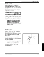
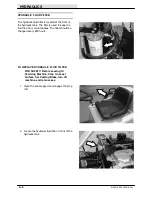
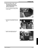
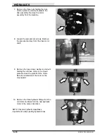
HYDRAULIC FLUID RESERVOIR
The reservoir is located on the right side of the
machine next to the engine.
A filler cap is mounted on top of the reservoir. It
has a built in breather and fluid level dipstick.
Replace the cap after every 800 hours of
operation.
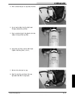
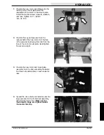
Check the hydraulic fluid level at
operating
temperature
daily. The dipstick is marked with full
and add markings to indicate the level of hydraulic
fluid in the reservoir. Cold fluid level is mid-point of
add and full lines.
Lubricate the filler cap gasket with a film of
hydraulic fluid before putting the cap back on the
reservoir.
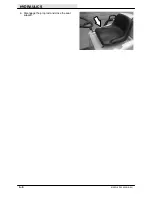
ATTENTION! Do not overfill the
hydraulic fluid reservoir or operate the
machine with a low level of hydraulic
fluid in the reservoir. Damage to the
machine hydraulic system may result.
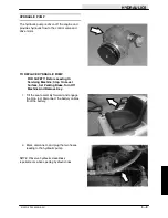
Drain and refill the hydraulic fluid reservoir with
new hydraulic fluid every 800 hours of operation.
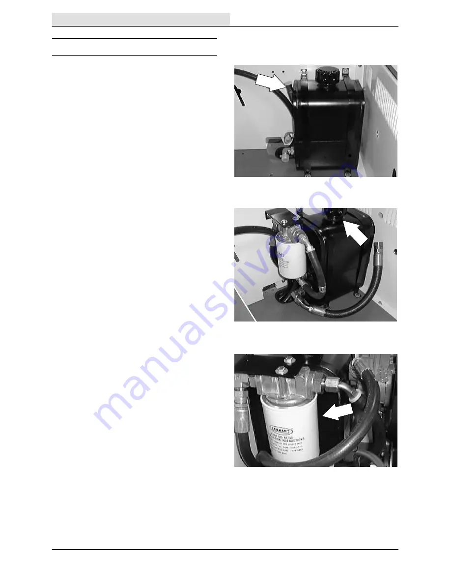
NOTE: When the hydraulic filter bypass light
(optional) comes on, replace the filter, and change
the hydraulic fluid as soon as possible.
The hydraulic fluid filter is located in front of the
hydraulic reservoir near the rear of the engine
compartment. Replace the filter element every
800 hours of operation.
Содержание 6100 G/LP
Страница 1: ...330235 Rev 02 9 01 Service Manual 6100 G LP ...
Страница 4: ...GENERAL INFORMATION 1 2 6100 G LP 330235 9 01 ...
Страница 18: ...CHASSIS 2 2 6100 G LP 330235 9 00 ...
Страница 27: ...CHASSIS 2 11 6100 G LP 330235 9 00 7 Remove the hub assembly from the tire assembly ...
Страница 72: ...CHASSIS 2 56 6100 G LP 330235 9 00 ...
Страница 74: ...SWEEPING 3 2 6100 G LP 330235 9 00 ...
Страница 152: ...ELECTRICAL 4 2 6100 G LP 330235 9 00 ...
Страница 175: ...ELECTRICAL 4 25 6100 G LP 330235 9 01 ...
Страница 176: ...ELECTRICAL 4 26 6100 G LP 330235 9 01 ELECTRICAL SCHEMATIC GAS 1 2 3 4 ...
Страница 177: ...ELECTRICAL 4 27 6100 G LP 330235 9 01 ELECTRICAL SCHEMATIC GAS 1 2 3 4 ...
Страница 178: ...ELECTRICAL 4 28 6100 G LP 330235 9 01 ELECTRICAL SCHEMATIC LP 1 2 3 4 ...
Страница 179: ...ELECTRICAL 4 29 6100 G LP 330235 9 01 ELECTRICAL SCHEMATIC LP 1 2 3 4 ...
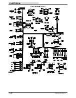
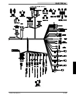
Страница 180: ...ELECTRICAL 4 30 6100 G LP 330235 9 01 WIRE DIAGRAM GAS LP ...
Страница 181: ...ELECTRICAL 4 31 6100 G LP 330235 9 01 WIRE DIAGRAM GAS LP ...
Страница 182: ...ELECTRICAL 4 32 6100 G LP 330235 9 01 ...
Страница 190: ...ELECTRICAL 4 40 6100 G LP 330235 9 00 ...
Страница 192: ...HYDRAULICS 5 2 6100 G LP 330235 9 00 ...
Страница 198: ...HYDRAULICS 5 8 6100 G LP 330235 9 00 9 Disengage the prop rod and close the seat support ...
Страница 205: ...HYDRAULICS 5 15 6100 G LP 330235 9 00 10 Disengage the seat rod and close the seat assembly ...
Страница 217: ...HYDRAULICS 5 27 6100 G LP 330235 9 00 HYDRAULIC SCHEMATIC ...
Страница 218: ...HYDRAULICS 5 28 6100 G LP 330235 9 00 OUT IN B A B A HYDRAULIC HOSE DIAGRAM ...
Страница 220: ...HYDRAULICS 5 30 6100 G LP 330235 9 00 ...
Страница 221: ......
Страница 222: ......
Страница 223: ......
Страница 224: ......
Страница 225: ......
Страница 226: ......
Страница 227: ......
Страница 228: ......
Страница 229: ......
Страница 230: ......
Страница 231: ......
Страница 232: ......
Страница 233: ......
Страница 234: ......
Страница 235: ......
Страница 236: ......
Страница 237: ......
Страница 238: ......
Страница 239: ......
Страница 240: ......
Страница 241: ......
Страница 242: ......
Страница 243: ......
Страница 244: ......
Страница 245: ......
Страница 246: ......
Страница 247: ......
Страница 248: ......
Страница 249: ......
Страница 250: ......
Страница 252: ...ENGINE GAS LP 6 2 6100 G LP 330235 9 00 ...
Страница 274: ...ENGINE GAS LP 6 24 6100 G LP 330235 9 00 ...


