


MAINTENANCE
1550 Gas/LPG/Diesel MM283 (9--01)
3--50
BRAKES AND TIRES
SERVICE BRAKES
The service brakes are hydraulically activated by
a master brake cylinder.
Check the master brake cylinder fluid level after
every 400 hours of operation and add brake fluid
as needed. The master brake cylinder is located
at the front of the machine. Open the front
compartment door for access to the master
cylinder.
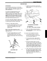
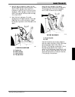
If necessary, adjust brake linkage as follows:
adjust clevis on master cylinder push rod so that
brake pedal is in a horizontal position when the
cylinder push rod starts to engage the cylinder
piston.
C
B
A
D
F
G
E
00105
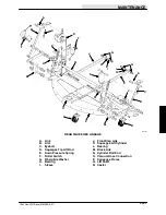
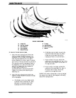
BRAKE SYSTEM COMPONENTS
A. Brake Pedal
B. Shaft
C. Pin
D. Master Brake Cylinder
E. Brake Line
F. Push Rod
G. Clevis
Brakes require bleeding whenever air enters the
system, lowering the effective braking pressure.
Air can enter when the master cylinder or wheel
cylinders are serviced or if the fluid in the
reservoir runs dry. Air can also enter through a
leaky brake line or hose. Find the leaking line and
replace it before bleeding.
Whenever handling brake fluid, do not get any on
the brake pads, brake discs, calipers, or body
paint. Brake pads will be permanently damaged,
requiring replacement. Body paint can be
damaged also unless you wipe the area with a
clean cloth and wash it with a soapy solution
immediately.
1. Make sure that the brake fluid reservoir is
full and that the vent in the cap is open.
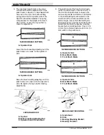
2. Connect a plastic or rubber tube to the
bleeder valve on the left front wheel.
Suspend the other end of the tube in a jar or
bottle filled with a few inches of brake fluid.
During the remaining steps, keep this end
submerged at all times and never let the
level in the brake fluid reservoir drop below
one half full.
3. Open the bleeder valve and plug on the left
front wheel about one turn. Have an
assistant press the brake pedal slowly to the
floor. As soon as the pedal is all the way
down, close the bleeder valve and let the
pedal up. Repeat this step as many times as
necessary, until fluid with no air bubbles
exits from the tube.
4. Bleed the right front wheel in the same
manner as described in the steps above.
Keep checking the brake fluid reservoir to be
sure it doesn’t run out of fluid.
5. When all wheels are bled, discard the brake
fluid in the jar or bottle; never reuse such
fluid.
6. Top up the brake fluid reservoir with clean
fluid.
Содержание 1550
Страница 16: ...SPECIFICATIONS 1550 Gas LPG Diesel MM283 6 91 1 2 ...
Страница 100: ...APPENDIX 1550 Gas LPG Diesel MM283 6 91 4 2 ...
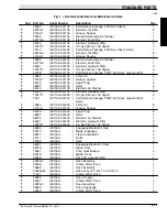
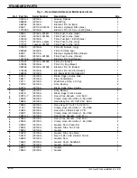
Страница 112: ...STANDARD PARTS 1550 Gas LPG Diesel MM283 11 07 6 6 ...
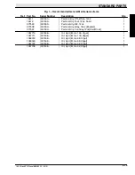
Страница 168: ...STANDARD PARTS 1550 Gas LPG Diesel MM283 9 01 6 62 Fig 36 Engine Muffler Group 001000 001423 5 8 4 3 2 1 5 9 3 6 7 ...
Страница 202: ...STANDARD PARTS 1550 Gas LPG Diesel MM283 9 01 6 96 Fig 55 Electrical Schematic Options 001000 001505 06182 550 1550 ...
Страница 203: ...STANDARD PARTS 6 97 1550 Gas LPG Diesel MM283 2 06 Fig 56 Electrical Schematic Specials 001000 001505 00363 550 1550 ...
Страница 215: ...STANDARD PARTS 6 109 1550 Gas LPG Diesel MM283 11 07 Fig 59 Electrical Schematic 001538 1013552 550 1550 G LP Impco ...
Страница 216: ...STANDARD PARTS 1550 Gas LPG Diesel MM283 11 07 6 110 Fig 59 Electrical Schematic 001538 Gas Engine Harness Schematic ...
Страница 217: ...STANDARD PARTS 6 111 1550 Gas LPG Diesel MM283 11 07 Fig 59 Electrical Schematic 001538 Gas Engine Harness Schematic ...
Страница 218: ...STANDARD PARTS 1550 Gas LPG Diesel MM283 11 07 6 112 Fig 59 Electrical Schematic 001538 Gas Engine Harness Schematic ...
Страница 222: ...STANDARD PARTS 1550 Gas LPG Diesel MM283 9 01 6 116 Fig 61 Electrical Wire Harnesses Group 001000 001505 2 3 1 ...
Страница 223: ...STANDARD PARTS 6 117 1550 Gas LPG Diesel MM283 9 01 Fig 61 Electrical Wire Harnesses Group 001000 001505 4 5 ...
Страница 224: ...STANDARD PARTS 1550 Gas LPG Diesel MM283 8 02 6 118 Fig 61 Electrical Wire Harnesses Group 001000 001505 6 ...
Страница 226: ...STANDARD PARTS 1550 Gas LPG Diesel MM283 2 05 6 120 Fig 62 Electrical Wire Harnesses Group Gas LPG 001508 1 ...
Страница 227: ...STANDARD PARTS 6 121 1550 Gas LPG Diesel MM283 2 05 Fig 62 Electrical Wire Harnesses Group Gas LPG 001508 2 ...
Страница 228: ...STANDARD PARTS 1550 Gas LPG Diesel MM283 2 05 6 122 Fig 62 Electrical Wire Harnesses Group Gas LPG 001508 3 ...
Страница 229: ...STANDARD PARTS 6 123 1550 Gas LPG Diesel MM283 2 05 Fig 62 Electrical Wire Harnesses Gas LPG Group 001508 4 5 ...
Страница 230: ...STANDARD PARTS 1550 Gas LPG Diesel MM283 2 05 6 124 Fig 62 Electrical Wire Harnesses Group Gas LPG 001508 20 ...
Страница 234: ...STANDARD PARTS 1550 Gas LPG Diesel MM283 8 08 6 128 Fig 62 Electrical Wire Harnesses Group Gas LPG 001508 28 27 ...
Страница 235: ...STANDARD PARTS 6 129 1550 Gas LPG Diesel MM283 3 11 Fig 62 Electrical Wire Harnesses Group Gas LPG 001508 29 ...
Страница 237: ...STANDARD PARTS 6 131 1550 Gas LPG Diesel MM283 3 11 ...
Страница 243: ...STANDARD PARTS 6 137 1550 Gas LPG Diesel MM283 8 02 Fig 66 Hydraulic Schematic 001000 001103 06164 550 1550 ...
Страница 286: ...STANDARD PARTS 1550 Gas LPG Diesel MM283 8 02 6 180 ...
Страница 301: ...LPG PARTS 7 15 1550 Gas LPG Diesel MM283 11 07 ...
Страница 359: ...DIESEL PARTS 8 49 1550 Gas LPG Diesel MM283 2 06 Fig 30 Electrical Schematic Diesel 001000 001423 06182 550 1550 D ...
Страница 363: ...DIESEL PARTS 8 53 1550 Gas LPG Diesel MM283 2 05 ...
Страница 364: ...DIESEL PARTS 1550 Gas LPG Diesel MM283 2 05 8 54 Fig 32 Electrical Schematic Diesel 001508 2 3 1 1013549 550 1550 D CAT ...
Страница 365: ...DIESEL PARTS 8 55 1550 Gas LPG Diesel MM283 2 05 Fig 32 Electrical Schematic Diesel 001508 1 2 3 1013549 550 1550 D CAT ...
Страница 366: ...DIESEL PARTS 1550 Gas LPG Diesel MM283 2 05 8 56 Fig 32 Electrical Schematic Diesel 001508 1013549 550 1550 D CAT ...
Страница 367: ...DIESEL PARTS 8 57 1550 Gas LPG Diesel MM283 2 05 Fig 33 Electrical Wire Harnesses Group Diesel 001508 1 ...
Страница 368: ...DIESEL PARTS 1550 Gas LPG Diesel MM283 2 05 8 58 Fig 33 Electrical Wire Harnesses Group Diesel 001508 1 ...
Страница 369: ...DIESEL PARTS 8 59 1550 Gas LPG Diesel MM283 2 05 Fig 33 Electrical Wire Harnesses Group Diesel 001508 2 ...
Страница 370: ...DIESEL PARTS 1550 Gas LPG Diesel MM283 2 05 8 60 Fig 33 Electrical Wire Harnesses Group Diesel 001508 3 ...
Страница 371: ...DIESEL PARTS 8 61 1550 Gas LPG Diesel MM283 2 05 Fig 33 Electrical Wire Harnesses Group Diesel 001508 4 5 ...
Страница 372: ...DIESEL PARTS 1550 Gas LPG Diesel MM283 2 05 8 62 Fig 33 Electrical Wire Harnesses Group Diesel 001508 6 ...
Страница 378: ...DIESEL PARTS 1550 Gas LPG Diesel MM283 2 05 8 68 ...
Страница 436: ...BREAKDOWNS 1550 Gas LPG Diesel MM283 8 02 10 38 ...
Страница 440: ...CONTINENTAL ENGINE BREAKDOWN GASOLINE LPG 1550 Gas LPG Diesel MM283 2 95 11 4 Fig 2 Cylinder Head Group ...
Страница 456: ...CONTINENTAL ENGINE BREAKDOWN GASOLINE LPG 1550 Gas LPG Diesel MM283 2 95 11 20 ...
Страница 470: ...61697 CONTINENTAL ENGINE BREAKDOWN DIESEL 1550 Gas LPG Diesel MM283 9 01 13 2 Fig 1 Engine Block Group ...
Страница 474: ...61697 CONTINENTAL ENGINE BREAKDOWN DIESEL 1550 Gas LPG Diesel MM283 9 01 13 6 Fig 3 Cylinder Head Group ...
Страница 488: ...65951 CONTINENTAL ENGINE BREAKDOWN DIESEL 1550 Gas LPG Diesel MM283 2 95 14 2 Fig 1 Engine Block Group ...
Страница 492: ...65951 CONTINENTAL ENGINE BREAKDOWN DIESEL 1550 Gas LPG Diesel MM283 2 95 14 6 Fig 3 Cylinder Head Group ...
Страница 534: ...PERKINS ENGINE BREAKDOWN DIESEL 1550 Gas LPG Diesel MM283 9 01 15 30 ...
Страница 562: ...1011676 CAT ENGINE BREAKDOWN DIESEL 1550 Gas LPG Diesel MM283 2 05 16 28 ...