OPERATION
1550 Gas/LPG/Diesel MM283 (2--06)
2--12
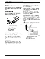
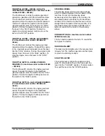
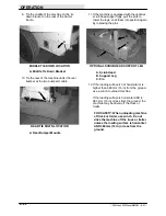
SQUEEGEE SWITCH
The squeegee switch, in conjunction with a
hydraulic flow sensing device, and the scrub
brush lever, controls the position of the rear
squeegee.
To raise the squeegee, flip the switch toggle
forward into the “Squeegee Up” position. This
position cannot be overridden by the hydraulic
flow sensing device.
To lower the squeegee, flip the switch toggle back
into the “Down” position. The squeegee will lower
when the machine starts moving in the forward
direction. When traveling in the reverse direction,
the hydraulic flow sensing device overrides the
squeegee switch and raises the rear squeegee.
This prevents the rear squeegees from being
damaged when traveling in reverse. The
squeegee switch should always be in the “Down”
position when scrubbing.
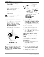
SCRUB BRUSH LEVER
The scrub brush lever controls the scrub brush
motors. To start the scrub brushes rotating in their
normal direction, pull the lever into the “ON”
position. To stop brush rotation, move the lever
into the “OFF” position.
To start the scrub brushes rotating opposite their
normal direction for double scrubbing, push the
lever into the “REVERSE” position.
SCRUB HEAD POSITION LEVER
The scrub head position lever controls the
position of the scrub head. To raise the scrub
head, pull the lever back into the “RAISE”
position. To stop scrub head movement move the
lever to the “HOLD” position. To lower the scrub
head, push the lever into the “LOWER” position.
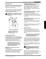
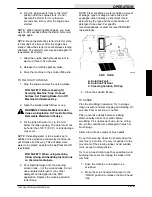
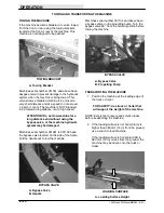
SRS LIQUID LOW LEVEL LAMPS
The SRS liquid low level lamps include two
indicating lamps. The cleaning solution lamp lights
when the cleaning solution level is low. The
recycling solution lamp lights when the recycling
solution is low.
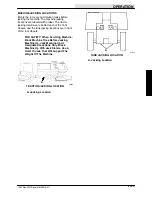
A
B
C
00351
SRS CONTROL PANEL
A. Liquid Low Level Indicator Lamps
B. Cleaning Solution Flow Knob
C. SRS Pump System Fuse (For
machines below serial number 001508)
C. SRS Pump System Circuit Breaker
(For machines serial number 001508
and above)
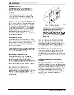
SRS CLEANING SOLUTION FLOW KNOB
The SRS cleaning solution flow knob controls
the pumping of cleaning solution into the solution
flow to the floor. The “LOW”, “MED”, and “HI”
levels indicate the rate of cleaning solution flow.
The “LOW” level causes the pump to deliver
one-fourth flow capacity, “MED” level one-half
capacity, and “HI” level full pump capacity of
cleaning solution into the solution flow to the floor.
The “OFF” position shuts off the cleaning solution
flow.
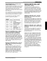
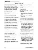
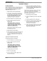
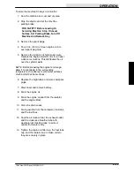
ENGINE CHOKE KNOB -- CONTINENTAL
ENGINES
The engine choke knob is present on gasoline
powered machines. The knob controls the engine
choke. To aid the starting of a cold engine, close
the engine choke by pulling the knob out. After the
engine has warmed up, push the knob in to open
the engine choke, allowing the engine to run
normally at its operating temperature and speed.
Using the choke on a warm engine is not
necessary.
Содержание 1550
Страница 16: ...SPECIFICATIONS 1550 Gas LPG Diesel MM283 6 91 1 2 ...
Страница 100: ...APPENDIX 1550 Gas LPG Diesel MM283 6 91 4 2 ...
Страница 112: ...STANDARD PARTS 1550 Gas LPG Diesel MM283 11 07 6 6 ...
Страница 168: ...STANDARD PARTS 1550 Gas LPG Diesel MM283 9 01 6 62 Fig 36 Engine Muffler Group 001000 001423 5 8 4 3 2 1 5 9 3 6 7 ...
Страница 202: ...STANDARD PARTS 1550 Gas LPG Diesel MM283 9 01 6 96 Fig 55 Electrical Schematic Options 001000 001505 06182 550 1550 ...
Страница 203: ...STANDARD PARTS 6 97 1550 Gas LPG Diesel MM283 2 06 Fig 56 Electrical Schematic Specials 001000 001505 00363 550 1550 ...
Страница 215: ...STANDARD PARTS 6 109 1550 Gas LPG Diesel MM283 11 07 Fig 59 Electrical Schematic 001538 1013552 550 1550 G LP Impco ...
Страница 216: ...STANDARD PARTS 1550 Gas LPG Diesel MM283 11 07 6 110 Fig 59 Electrical Schematic 001538 Gas Engine Harness Schematic ...
Страница 217: ...STANDARD PARTS 6 111 1550 Gas LPG Diesel MM283 11 07 Fig 59 Electrical Schematic 001538 Gas Engine Harness Schematic ...
Страница 218: ...STANDARD PARTS 1550 Gas LPG Diesel MM283 11 07 6 112 Fig 59 Electrical Schematic 001538 Gas Engine Harness Schematic ...
Страница 222: ...STANDARD PARTS 1550 Gas LPG Diesel MM283 9 01 6 116 Fig 61 Electrical Wire Harnesses Group 001000 001505 2 3 1 ...
Страница 223: ...STANDARD PARTS 6 117 1550 Gas LPG Diesel MM283 9 01 Fig 61 Electrical Wire Harnesses Group 001000 001505 4 5 ...
Страница 224: ...STANDARD PARTS 1550 Gas LPG Diesel MM283 8 02 6 118 Fig 61 Electrical Wire Harnesses Group 001000 001505 6 ...
Страница 226: ...STANDARD PARTS 1550 Gas LPG Diesel MM283 2 05 6 120 Fig 62 Electrical Wire Harnesses Group Gas LPG 001508 1 ...
Страница 227: ...STANDARD PARTS 6 121 1550 Gas LPG Diesel MM283 2 05 Fig 62 Electrical Wire Harnesses Group Gas LPG 001508 2 ...
Страница 228: ...STANDARD PARTS 1550 Gas LPG Diesel MM283 2 05 6 122 Fig 62 Electrical Wire Harnesses Group Gas LPG 001508 3 ...
Страница 229: ...STANDARD PARTS 6 123 1550 Gas LPG Diesel MM283 2 05 Fig 62 Electrical Wire Harnesses Gas LPG Group 001508 4 5 ...
Страница 230: ...STANDARD PARTS 1550 Gas LPG Diesel MM283 2 05 6 124 Fig 62 Electrical Wire Harnesses Group Gas LPG 001508 20 ...
Страница 234: ...STANDARD PARTS 1550 Gas LPG Diesel MM283 8 08 6 128 Fig 62 Electrical Wire Harnesses Group Gas LPG 001508 28 27 ...
Страница 235: ...STANDARD PARTS 6 129 1550 Gas LPG Diesel MM283 3 11 Fig 62 Electrical Wire Harnesses Group Gas LPG 001508 29 ...
Страница 237: ...STANDARD PARTS 6 131 1550 Gas LPG Diesel MM283 3 11 ...
Страница 243: ...STANDARD PARTS 6 137 1550 Gas LPG Diesel MM283 8 02 Fig 66 Hydraulic Schematic 001000 001103 06164 550 1550 ...
Страница 286: ...STANDARD PARTS 1550 Gas LPG Diesel MM283 8 02 6 180 ...
Страница 301: ...LPG PARTS 7 15 1550 Gas LPG Diesel MM283 11 07 ...
Страница 359: ...DIESEL PARTS 8 49 1550 Gas LPG Diesel MM283 2 06 Fig 30 Electrical Schematic Diesel 001000 001423 06182 550 1550 D ...
Страница 363: ...DIESEL PARTS 8 53 1550 Gas LPG Diesel MM283 2 05 ...
Страница 364: ...DIESEL PARTS 1550 Gas LPG Diesel MM283 2 05 8 54 Fig 32 Electrical Schematic Diesel 001508 2 3 1 1013549 550 1550 D CAT ...
Страница 365: ...DIESEL PARTS 8 55 1550 Gas LPG Diesel MM283 2 05 Fig 32 Electrical Schematic Diesel 001508 1 2 3 1013549 550 1550 D CAT ...
Страница 366: ...DIESEL PARTS 1550 Gas LPG Diesel MM283 2 05 8 56 Fig 32 Electrical Schematic Diesel 001508 1013549 550 1550 D CAT ...
Страница 367: ...DIESEL PARTS 8 57 1550 Gas LPG Diesel MM283 2 05 Fig 33 Electrical Wire Harnesses Group Diesel 001508 1 ...
Страница 368: ...DIESEL PARTS 1550 Gas LPG Diesel MM283 2 05 8 58 Fig 33 Electrical Wire Harnesses Group Diesel 001508 1 ...
Страница 369: ...DIESEL PARTS 8 59 1550 Gas LPG Diesel MM283 2 05 Fig 33 Electrical Wire Harnesses Group Diesel 001508 2 ...
Страница 370: ...DIESEL PARTS 1550 Gas LPG Diesel MM283 2 05 8 60 Fig 33 Electrical Wire Harnesses Group Diesel 001508 3 ...
Страница 371: ...DIESEL PARTS 8 61 1550 Gas LPG Diesel MM283 2 05 Fig 33 Electrical Wire Harnesses Group Diesel 001508 4 5 ...
Страница 372: ...DIESEL PARTS 1550 Gas LPG Diesel MM283 2 05 8 62 Fig 33 Electrical Wire Harnesses Group Diesel 001508 6 ...
Страница 378: ...DIESEL PARTS 1550 Gas LPG Diesel MM283 2 05 8 68 ...
Страница 436: ...BREAKDOWNS 1550 Gas LPG Diesel MM283 8 02 10 38 ...
Страница 440: ...CONTINENTAL ENGINE BREAKDOWN GASOLINE LPG 1550 Gas LPG Diesel MM283 2 95 11 4 Fig 2 Cylinder Head Group ...
Страница 456: ...CONTINENTAL ENGINE BREAKDOWN GASOLINE LPG 1550 Gas LPG Diesel MM283 2 95 11 20 ...
Страница 470: ...61697 CONTINENTAL ENGINE BREAKDOWN DIESEL 1550 Gas LPG Diesel MM283 9 01 13 2 Fig 1 Engine Block Group ...
Страница 474: ...61697 CONTINENTAL ENGINE BREAKDOWN DIESEL 1550 Gas LPG Diesel MM283 9 01 13 6 Fig 3 Cylinder Head Group ...
Страница 488: ...65951 CONTINENTAL ENGINE BREAKDOWN DIESEL 1550 Gas LPG Diesel MM283 2 95 14 2 Fig 1 Engine Block Group ...
Страница 492: ...65951 CONTINENTAL ENGINE BREAKDOWN DIESEL 1550 Gas LPG Diesel MM283 2 95 14 6 Fig 3 Cylinder Head Group ...
Страница 534: ...PERKINS ENGINE BREAKDOWN DIESEL 1550 Gas LPG Diesel MM283 9 01 15 30 ...
Страница 562: ...1011676 CAT ENGINE BREAKDOWN DIESEL 1550 Gas LPG Diesel MM283 2 05 16 28 ...

