background image

13 

 
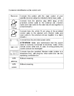
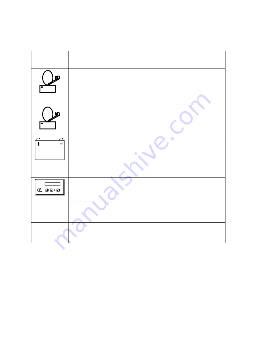
Connector identification at the control unit: 
 

Receiver  Connect this socket with the input socket of your 

satellite receiver using the included shorter coax cable. 


F-Plug 

Connect here the antenna plug (BNC plug) of the 
provided control cable to the external unit. (Control 
cable and coax cable to the external unit are together in 
a black sheath.) 


Connect here the white 15 pin plug of the provided 
control cable to the external unit. (Control cable and 
coax cable to the external unit are together in a black 
sheath.) 


30/3 1/15 

Connect here the provided power cable.  

ATTENTION! 

Make sure beforehand that the power 

cable is correctly connected to electricity mains of the 
vehicle at the other end; in case of wrong polarity the 
control unit can be destroyed! 


Connect here the provided Western cable (similar to a 
telephone line), and plug the other cable end into the 
operating control device. 

GPS 

antenna 

Without meaning 

GPS 

extern 

Without meaning 


Содержание Oyster Vision II

Страница 1: ...1 Assembly Instructions Oyster Vision II Issue Mai 2006 ...

Страница 2: ...nt for point successively Note This is a sensitive device Do not tear at the dish arm Do not manually lift or turn the dish arm the dish arm may only be moved by the motor Only raise at plastic screen or aluminium plate The screws at the plastic housing may be loosened only by the manufacturer of the unit Caution Never grip into the range of the external unit while it is moving Note for operation ...

Страница 3: ...t white coax cable together with control cable in black sheath Coax cable for connection of your satellite receiver with the control unit Western cable connection between control unit and operating control device Power cable control unit Operating instructions Assembly instructions In addition required for television reception Satellite receiver not comprised in the scope of delivery ...

Страница 4: ...ials and packaging auxiliaries are recyclable and must in principle be supplied to material recycling Packaging materials e g plastic bags should not be made accessible to children Please also observe the notes regarding environmental protection on page 20 ...

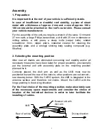
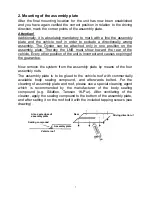
Страница 5: ...g Sikaflex 2 Selecting the mounting position After now all doubts are eliminated concerning roof stability and or all necessary measures have been taken for proper assembly provisionally put the external unit with assembly plate on the mounting position planned for it Correctly placed the dish arm as well as the LNB must now be positioned toward the rear of the vehicle other positions are not corr...

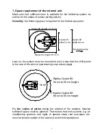
Страница 6: ...cle see drawing on previous page For the radius of action during the rotation of the antenna likewise sufficient space must be planned That means that roof systems e g air conditioning systems roof lights in opened state roof suit cases etc must be located outside of the radius of action indicated above r e t s y O width 72 cm Oyster 65 Oyster 85 width 92 cm Driving direction Oyster 85 length 111 ...

Страница 7: ...position of the unit is incorrect and causes expiring of the guarantee Now remove the system from the assembly plate by means of the four assembly nuts The assembly plate is to be glued to the vehicle roof with commercially available body sealing compound and afterwards bolted For the cleaning of assembly plate and roof please use a special cleaning agent which is recommended by the manufacturer o...

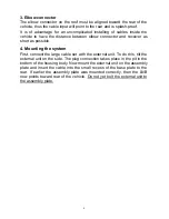
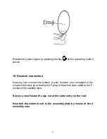
Страница 8: ...s short as possible 4 Mounting the system First connect the large cable set with the external unit To do this tilt the external unit on the side The plug connection takes place in the pit in the bottom of the housing body Now mount the external unit on the assembly plate and insert the cable into the small recess of the base plate to the rear If earlier the assembly plate was mounted correctly the...

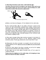
Страница 9: ...ntilating of the cleaner apply the sealing compound to the bottom of the assembly plate and after setting it on the roof bolt it with the included 4 tapping screws c Now apply strongly sticking body sealing compound to the bottom of the elbow connector and mount it on the assembly position small aluminium plate Thereby pay attention to correct seat of the O ring d Afterwards the elbow connector is...

Страница 10: ...elbow connector downwards to the control unit b For the cable distance between the external unit and the elbow connector on the vehicle roof you can use the commercially available cable troughs c Should the cable be too long within the vehicle you can coil it up ...

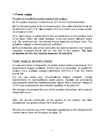
Страница 11: ...use protection of this line must be between 10 and 20 A Power supply in caravans trailers In caravans there is frequently no stable and or battery backed up 12 V board power supply available In this case it is necessary to supply the system via a suitable voltage transformer 220 V 12 V from the mains power net Do not use under any circumstances battery chargers simple transformers or non stabilize...

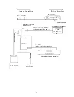
Страница 12: ...ion Pin 15 D s c h w a r z red brow Elbow connector External unit Assembly plate Control unit Operating control device Western cable length 6 5 m from operating control device Coax cable Length 1 5 m from control unit Receive not comprised in scope of delivery Rear of the vehicle Driving direction ...

Страница 13: ... 15 pin plug of the provided control cable to the external unit Control cable and coax cable to the external unit are together in a black sheath 30 3 1 15 Connect here the provided power cable ATTENTION Make sure beforehand that the power cable is correctly connected to electricity mains of the vehicle at the other end in case of wrong polarity the control unit can be destroyed Connect here the pr...

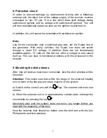
Страница 14: ...addition there are not immediately available approx 12 volts on this line but often a voltage is only slowly built up This can lead to functional problems with the processor in the receiver 9 Mounting the dish antenna After now all devices have been connected next the dish antenna will be mounted Attention First make sure that within the range of the external rotating unit no tools or the like pre...

Страница 15: ...u can connect the system to your receiver not comprised in the scope of delivery by screwing the F plug at the white coax cable to the F socket of the satellite input Now you must fasten the cap nut at the cable entry on the roof Now bolt the external unit to the assembly plate by means of the 4 assembly nuts ...

Страница 16: ...rect channel has been found You should now store this channel at a program place of your choice Or Connection via the TV Scart socket with a Scart cable generally available in stores not comprised in the scope of delivery Over this connector a stereophonic sound play back is possible You do not need to connect the provided TV coax cable in this case You need to do nothing further than to plug the ...

Страница 17: ...already used the system at the same location and in the same vehicle position then it will receive immediately in the last reception position without searching German language programming is usually transmitted over the Astra1 satellite which can also be received in most parts of Europe with a dish size of 65 cm In some regions e g in parts of Greece or in Turkey the Astra satellite transmits no s...

Страница 18: ... need a wrench SW 13 It is not necessary to dismantle the cable Proceed as follows Unscrew the 4 nuts M8 with which the system is bolted to the assembly plate Lift the system a little bit press on the nose of the 15 pin plug and pull it off Turn at the BNC plug of the coaxial cable and pull it off Now you can lift off the system In order to assemble the system again proceed in reverse order ...

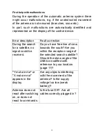
Страница 19: ...uring the search for a satellite no signal could be received Do you have free line of view towards the south Are you within the reception range of the selected search satellite Should the skew angle of the LNB be modified with reference to your location page 11 Y motor error or X motor error appears in the display Are any objects interfering with the movement of the antenna Is the supply voltage t...

Страница 20: ...rical and electronic devices The symbol on the product in the instructions or at the packaging refers to this The materials are reusable in accordance with their identification With recycling material reutilization or other forms of reutilization of old devices you make an important contribution to the protection of our environment Please inquire the respective disposal locations at your local adm...

Страница 21: ...e call our service hotline Telephone 49 7237 48550 We are at your service Monday Thursday 9 00 12 00 a m and 1 00 4 30 p m and Friday 9 00 a m 2 00 p m We hope you will enjoy your Oyster Vision II ten Haaft GmbH Oberer Strietweg 8 D 75245 Neulingen Göbrichen info ten haaft de www ten haaft de ...

Отзывы: