Copyright20 Tempest Technology Corporation (Rev: 8.10.2020.1)
20
Control Panel Feature
Description
1
Lift/Tilt Hydro Pressure
Shows hydraulic oil pressure in the auxiliary pump system
(Scissors lift, Tilt).
2
Engine Control / Data
Display
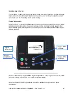
Use to start the engine, set engine speed, and to turn the
engine off. Shows engine RPM, temperature, volts, oil
pressure. Used to access Engine Control Module (ECM) Data.
3 Clinometer
NEVER
/- 5 degrees longitudinal slope (front to back)
or +/-2 degrees lateral slope (side to side).
4 Emergency Stop
This will shut down the engine and hydraulic system.
5
Emergency Stop Warning
Light
Indicates that one of the Emergency Stop switches is
activated.
6 Compartment
Light Switch
Turns on two interior compartment lights.
7
Fan Run (Start/Stop)
Switch
Turns on the fan motor hydraulic circuit.
8
Fan Tilt Forward/Backward
Turn
TILT
switch to
DOWN
to tilt fan down,
UP
to tilt fan up.
9
Fan/Engine Speed Control
After the fan has been engaged, the fan RPM can be adjusted
with the FAN SPEED CONTROL. To
increase the fan
speed
, turn the switch to
INC
. To
reduce fan speed
, turn the
switch to
DEC
.
10 Fan
Motor
Hydro Pressure
Show hydraulic oil pressure in the fan motor hydraulic system.
11 Engine Fuel Gauge
Indicates the diesel fuel level.
12 Master Power Disconnect
Turns off all power to the control panel. The Master
Disconnect Switch should be OFF during storage of MVU.
13
Hydraulic Filter Warning
Light
Illuminates when the oil filter of the hydraulic system needs to
be changed.
14
Hydraulic Level Warning
Light
Illuminates when the oil level in the hydraulic tank is low.
15
Hydraulic Temperature
Warning Light
Illuminates when the temperature of the hydraulic oil reaches
190 degrees farenheit. Turn off ventalator and continue
running the engine until the temperature cools and the light
goes off. The hyraulic cooling fan starts when the oil
temperature reaches 145 degrees farenheit.
16 Scissors Lift Up/Down
Turn
LIFT
switch to
UP
to raise fan and to
DOWN
to lower fan.
Acoustic warning signal sounds during lowering function.
17 Fan Rotate Left/Right
Turn the
ROTATE
switch
CCW
(counter clockwise) or
CW
(clockwise), 360° continuous in either direction.
WARNING
:
DO NOT rotate ventilator while operating at high fan RPM.
Reduce fan speed before rotating.
18
Local/Remote Control
Switch
Set switch to LOCAL if using the control panel to operate MVU.
Set to REMOTE if using the remote control.


