background image

Copyright20 Tempest Technology Corporation     (Rev: 8.10.2020.1) 


31 

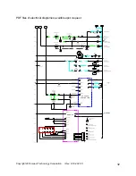
Electrical Wiring Diagrams


1

L3


L1

FU1

X1

BLK

TAS1

X1

WHT

OX

SS1

LT1

W

LT2

W

X3:1

BLK

X3:2

WHT

FU2

FIELD

X4:1

BLK

X4:2

WHT

X4:3

RED

X4:4

GRN

ROTATE

FU3

PB1

PB2

C1-1/20

A

C1-3/22

C

LT3

R

C1-2/21

B

C1-4/23

D


SV1A


SV2A

X2-24

GRN

X2-1

RED

X2-2


RED./WHT

SS2

SS3


SV2B

X2-3


RED/BLK

SS4

G

4

SV3A

X2-4

 WHT/BLK

SS5


SV3B

X2-5


BLK

SS6

C1-5

E

C1-6

F

C1-7

G

C1-5

E

C1-8

H

C1-9

J

26

26

26

26

26

R

R

R

R

R

R

R

R

R

R

R

SS7

SS8

C1-5

E

C1-16

S

C1-17

T

R

R

2

3

4

5

6

7

8

9

10

11

12

13

14

15

16

17

18

19

20

21

22

23

24

24VDC 

POS 

NEG 

LT5

C

45


Содержание MVU-60

Страница 1: ...information in this manual before operating the MVU For questions and additional information contact the Tempest Technology factory at Tempest Technology Corporation 4708 N Blythe Avenue Fresno Calif...

Страница 2: ...g Signs and Symbols 6 Safety Measures 7 MVU Specifications 14 Water Misting System 16 MVU Systems 17 Control Panel Features and Operation 19 Starting and Stopping Instructions 22 Fluids and Filters 24...

Страница 3: ...ht to make any changes or improvements that we consider to be appropriate Any obligation to earlier delivered models shall not be connected herewith Copyright 2020 by Tempest Technology Corp 4708 N Bl...

Страница 4: ...ze yourself with it Standard Equipment The operating instructions contain descriptions of standard and non standard equipment For this reason the equipment that you receive can deviate partially from...

Страница 5: ...y or damage to the MVU The Mobile Ventilation Unit is constructed with the latest state of the art technology and safety features Nevertheless it can be dangerous for the user if not operated properly...

Страница 6: ...n the operating instructions all safety warnings are marked with this sign It means that injury potential exists Follow all security warnings as well as the accident prevention instructions Meaning In...

Страница 7: ...mes Wear operator ear protection when standing near the diesel engine and ventilator The diesel engine which powers the hydraulic system can emit poisonous exhaust fumes Exhaust fumes can cause severe...

Страница 8: ...s turned off Do not refuel the MVU in a closed room The fumes are poisonous and explosive Always clean up spilled fuel Be especially careful of sparks open flame large heat radiation etc Only operate...

Страница 9: ...safety clothing Never operate the MVU when on a slope of more than 5 degrees longitudinal slope or 2 degrees lateral slope Never move the MVU or vehicle when fully elevated or during fan operation Obs...

Страница 10: ...perated in an explosive environment Work on the electrical system may only be performed by an electrician or by trained personnel under the direction and supervision of an electrician in accordance wi...

Страница 11: ...ry Explosion Danger Fire spark open flame and smoking are forbidden Avoid any spark sources when working with the cable and electric devices Avoid short circuits Personnel Warning Battery acid is extr...

Страница 12: ...ries that do not come from Tempest Technology Corporation or are not tested and approved by Tempest can adversely affect the durability and performance characteristics of the MVU and affect operator s...

Страница 13: ...1 13 Maintenance Support and Service If problems occur during the maintenance and service of the ventilator please contact Tempest Technology Corporation 4708 N Blythe Avenue Fresno CA 93722 Tel 559...

Страница 14: ...nted MVU Overall Specifications Total Height 148 inches Total Width 98 inches Total Length 308 inches Total Weight 17 200 pounds approximate Blower Assembly Shroud Diameter 60 inches Shroud Material S...

Страница 15: ...r On and RPM Gauges for hydraulic pressure Controls for ventilator scissors tilt and rotation Emergency shut down switch Master power disconnect switch Wired Remote Control Portable control box Ventil...

Страница 16: ...ring made from 1 1 2 diameter stainless steel tubing is mounted forward of the propeller inside the ventilator shroud A total of twelve evenly spaced 65 degree spray pattern nozzles on the ring provid...

Страница 17: ...ated when the clinometer exceeds either of the slope parameters listed below IMPORTANT Maximum lateral slope is two degrees 2O in either direction Maximum longitudinal slope is five degrees 5O in eith...

Страница 18: ...tures a rotation locking pin to prevent wear and tear on the rotation system during transport The locking pin must be released prior to operating the MVU The locking pin is located on the operator sid...

Страница 19: ...nometer 12 Master Power Disconnect 4 Emergency Stop 13 Hydraulic Filter Warning Light 5 Emergency Stop Warning Light 14 Hydraulic Level Warning Light 6 Compartment Light Switch 15 Hydraulic Temperatur...

Страница 20: ...EC 10 Fan Motor Hydro Pressure Show hydraulic oil pressure in the fan motor hydraulic system 11 Engine Fuel Gauge Indicates the diesel fuel level 12 Master Power Disconnect Turns off all power to the...

Страница 21: ...ntilator Tilt 3 Ventilator Lift 4 Fan Unit Rotate 5 Fan Speed 6 Emergency Shut Down Activates FAN SPEED CONTROL 5 below FWD Tilt Fan Down REV Tilt Fan Up UP Raise Fan DOWN Lower Fan LEFT Rotate Left R...

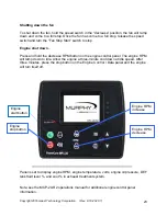
Страница 22: ...on for both local panel and remote control system Once the engine has warmed up press and hold the increase RPM button on the engine control panel The RPM will ramp up to 2200 RPM Set the Local Remote...

Страница 23: ...RPM button on the engine control panel The engine RPM will ramp down to idle Allow the engine a three minute cool down at idle speed After three minutes press the stop button on the Engine Control Dat...

Страница 24: ...Copyright20 Tempest Technology Corporation Rev 8 10 2020 1 24 Fuel DEF and Hydraulic Fluid Diesel tank filler cap DEF tank filler cap Hydraulic fluid tank filler cap In tank hydraulic filter...

Страница 25: ...accessed through the compartment on the left side of the MVU Engine Air Filter Diesel Filters Engine Oil Fill Spout Engine Oil Dipstick Engine Oil Filter Draining the engine oil From under the traile...

Страница 26: ...on system bearing via four grease zerks located on the inside face of the rotation bearing through the top center of the yoke See next page 4 Lubricate fan shaft bearings via the remote grease zerks l...

Страница 27: ...of cylinders Lift cylinders x 4 B Underside of Fan Housing x 2 C Rotation Bearing Zerk x 2 D Fan Tilt Bearings X2 IMPORTANT Lubricate with a high NLGI no Lithium base grease having rust inhibitors an...

Страница 28: ...ate the extension and retraction of the cylinder POTENTIAL CAUSE The electrical system 1 The Local Remote switch is in the wrong mode Check to make sure the switch is set to the correct position 2 Che...

Страница 29: ...5 Gauge is malfunctioning check analog gauge YELLOW LIGHT Hydraulic Oil Level 1 Oil level is low below sight glass 2 Gauge is malfunctioning RED LIGHT Emergency Fan Stop 1 Emergency switch at cabinet...

Страница 30: ...Rexroth RR00561284 Control Panel Switch Brand Part Number 3 Position Switch Tempest 582 001 2 Position Switch Tempest 582 002 Switch Keyed Start Tempest 582 003 3 Position Green Light Tempest 582 004...

Страница 31: ...ED X4 4 GRN ROTATE FU3 PB1 PB2 C1 1 20 A C1 3 22 C LT3 R C1 2 21 B C1 4 23 D SV1A SV2A X2 24 GRN X2 1 RED X2 2 RED WHT SS2 SS3 SV2B X2 3 RED BLK SS4 G 4 SV3A X2 4 WHT BLK SS5 SV3B X2 5 BLK SS6 C1 5 E...

Страница 32: ...11 BLU BLK X2 12 GRN BLK X2 13 GRN WHT X2 10 BLU C1 XX JP 46 X3 23 24 24 24 R R R R R 27 28 29 30 31 32 33 34 35 36 37 38 39 40 41 42 43 44 45 46 47 48 49 50 34 34 34 LT4 G LT4 G X2 9 WHT C1 24 V CAN...

Страница 33: ...Copyright20 Tempest Technology Corporation Rev 8 10 2020 1 33 Hydraulic Panel...

Страница 34: ...ion 4708 N Blythe Avenue Fresno CA 93722 USA t 1 559 277 7577 f 1 559 277 7579 response tempest us com www tempest us com All information provided in this operations manual is subject to change withou...

Отзывы: