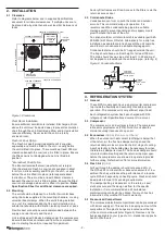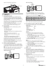
- 5 -
It is recommended that control is by Enthalpy (or by a
combination of dry and wet bulb temperatures) so that
free cooling is used without adding any heat load to the
building. This is a requirement of Australian NCC and NZ
Building Code. Control by dry bulb temperature alone is not
recommended as often, even though the outdoor dry bulb
temperature may be lower than that of the space, the total
heat content of the air can be higher thereby adding heat
load in the form of moisture content to the space.
If dry bulb temperature is used as the control method the
temperature must be set several degrees lower than the
space temperature to reduce the possibility of extra heat
load being introduced.
Air Quality (CO
2
) sensors can be used to proportionally
control the fresh and return air dampers (via the control
system).
In all situations the UC8 Unit Controller will allow the
compressors to operate with the economiser fresh air
damper open providing the refrigeration system is not
compromised.
The compressor(s) could be stopped from operating by
normal protection devices such as low suction temperature/
pressure or indoor coil frost protection and too many trips
of either fault could lead to a lock out of the compressor(s)
operation. Should this occur then a review of the control
settings may be necessary.
5. START-UP PROCEDURE
5.1 Before starting the compressor
1. Before working on the unit remove mains power from
the unit by opening the mains isolating switch.
2. Remove the shipping blocks from beneath each
compressor. Check that each compressor is securely
mounted.
3. Check the thermostat and/or other controls are
correctly wired to the unit.
4. Check tightness of electrical connections.
5. Check the air filters have been correctly installed, if
present.
6. Check that all indoor fan motors can freely rotate.
7. Apply mains power to the unit by closing the mains
isolating switch.
8. Check the supply voltage between each phase and
neutral.
9. Check air diffusers are open.
10. Before starting the compressors a four hour delay
period is required to allow the crankcase heaters to
drive any liquid refrigerant out of the compressor oil.
Mains power must be switched on during this four hour
delay period.
5.2 Commissioning
After the four hour delay period has expired (see step 10 in
section 5.1) complete the following procedure. You can use
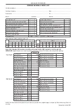
the Commissioning Sheet (refer back page) to help you.
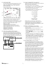
1. Place the UC8 controller in commissioning mode by
pressing and holding the SW3 push button (see Fig. 4)
until the display shows:
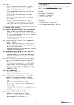
‘0’ [release] ‘1’ [long press] ‘t’; [short press] repeat
to find ‘c’, then [long press] to select.
This Commissioning mode ‘c’ reduces the waiting
times at start-up and between cycles.for the next
half hour, or until the controller is reset by removing
power.
2. Start compressor in Cooling mode.
3. Check the outdoor fan motor runs smoothly.
Note: The outdoor fan does not necessarily start rotating
immediately after the compressor is started. The fans
may run-on for a short period after the compressor
stops.
Outdoor fan stops during outdoor coil de-ice cycles.
4. Measure the current draw on each phase to the
compressor motor and to each fan motor. Check the
readings against the specified values in the wiring
diagram or specification sheet.
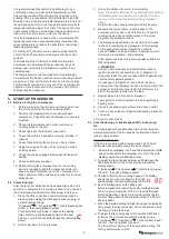
5. The display and pushbutton on the UC8 can be used
to check temperatures and pressures. Short presses
on the pushbutton cycles through the available
options. Table 1 on page 8 shows, in sequence, what
information is available – with examples.
Alternatively use a set of pressure gauges suitable for
R32 refrigerant.
!
WARNING
Under no circumstances shall potential sources of
ignition be used in the searching for or detection of
refrigerant leaks. If a leak is suspected, all naked flames
shall be removed/extinguished.
If a leakage of refrigerant is found which requires
brazing, all of the refrigerant shall be recovered from the
system, or isolated (by means of shut-off valves) in a
part of the system remote from the leak.
6. Repeat steps 2 to 5 for each compressor.
7. Test operation of the compressors when operating in
heating mode.
8. Check for desired supply air flow rate at each outlet.
9. Touch up any outdoor unit paintwork damage to prevent
corrosion.
10. Sign the check label.
5.3 Commissioning of variable speed (EC) indoor plug
fan
A unit equipped with variable speed (EC) indoor plug fan
allows adjustment of the fan speeds to obtain the desired
indoor supply airflows.
Using TZT-100 option
If the unit is controlled with a temperzone TZT-100 wall
thermostat then adjustments are made as follows:
i. Ensure the compressor is off and the thermostat or BMS
does not request for the compressor to start. The UC8
display should show a flashing dot (●).
ii. To adjust the fan High speed press and hold down the
SW3 push button on the UC8 circuit board until the
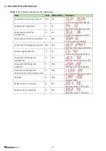
display shows:
‘0’ [release] ‘1’ [long press] ‘t’; [short press] repeat
to find ‘H’, then [long press] to select.
iii. The fan will start and run at High speed. The display
shows the fan control voltage for the High
speed setting; factory default value is 8.0V.
iv. Each following press on the SW3 push
button increases the indoor fan control voltage in steps
of 0.5V, up to a maximum of 10.0V. Pressing the push
button again when value 10.0 is shown returns the fan
control voltage down to the minimum value of 3.0V and
back up again.
v. When the desired setting for high fan speed is displayed,
[long press] to select and save. The controller then exits
the menu and the fan stops.
vi. To adjust the fan Low speed hold down the SW3 push
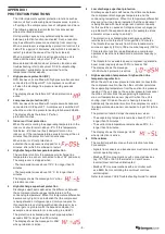
button on the circuit board until the display shows:
‘0’ [release] ‘1’ [long press] ‘t’; [short press] repeat
to find ‘L’, then [long press] to select.
The fan will start and run at the Low speed setting. The
factory default value is 5.0V.


