- 2 -
2. INSTALLATION
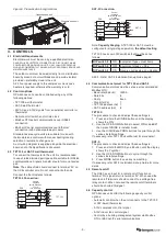
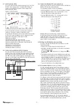
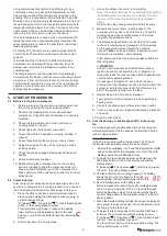
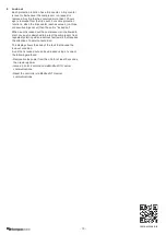
2.1 Clearance
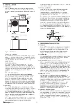
Refer to diagrams below and in supplied Specifications
document for minimum clearances. If multiple units are to
be placed side-by-side then allow at least 2m between coil
faces.
Figure 1. Clearances
Plant Room Installation
Ensure sufficient ventilation is installed. Discharge air from
above the unit must be ducted away to prevent recirculation
of air through the unit. Restricted airflow and/or recirculation
reduces efficiency. Never install the unit in a totally
enclosed room.
Fresh Air Cowl Option
The Fresh Air weathercowl (weatherhood) is supplied
separately and must be fitted to the unit – usually before
the unit is lifted in to place. There must be at least 300mm
clearance beneath the cowl once it is fitted in place. Ensure
the fitted cowl is not damaged when unit is lifted into
position.
*Economiser Cowl Option
The Economiser weathercowl (weatherhood) is larger
than the standard Fresh Air cowl and is supplied in kitset
form for on-site assembly and fitting to the unit – usually
before the unit is lifted into place (refer separate kitset
instructions). There must be at least 300mm clearance
beneath the cowl once it is fitted in place. Ensure the fitted
cowl is not damaged when unit is lifted into position. Refer
Specification Sheet for additional clearances required.
2.2 Mounting
The unit should be fastened to a firm flat horizontal base
using the holes supplied in the mounting channels, or using
universal beam clamps. When the unit is being installed
on a roof it is recommended that the unit is installed on a
substantial structure with vibration isolating mounts or pads.
Flexible duct connections are recommended between the
supply and return ducts and the unit.
Unit is shipped with blocks installed under the compressors.
Ensure these blocks are removed from the compressor feet
prior to starting the unit (not required for operation).
Factory filter frames are fitted. Access to the filters is via the
return air access door.
2.3 Condensate Drains
Condensation can form on both the indoor and outdoor
air coils. This is normal during unit operation. It is
recommended the condensate be piped to a suitable
drainage point to prevent ponding and/or slippery mould
growth around the base of the unit.
An optional outdoor coil drain tundish is available (part 060-
000-635) with 25mm OD stub. Alternatively, for a drip free
installation a separate drain tray beneath the unit could be
used to drain condensate to a suitable drainage point.
Condensate drains should be ‘U’ trapped outside the unit.
The trap should have a vertical height of at least 100 mm.
The drain should have a slope of at least 1 in 50 and must
not be piped to a level above the unit drain pipe. (refer fig. 2)
Figure 2. Condensate Drains
OPEN
DRAIN
MINIMUM
SLOPE
20 mm PER m
(1 IN 50)
100 mm
MINIMUM
200 mm
APPROX.
'U' TRAP
100 mm
APPROX.
VENT PIPE
FOR LONG
CONDENSATE
DRAIN RUNS
3. REFRIGERATION SYSTEM
3.1 General
These OPA models each have a single inverter compressor
to provide the flexibility and economy of variable speed
operation. The compressor is very efficient at part load.
Each refrigeration system has been charged with R32
refrigerant; refer Specifications document for amount.
3.2 Compressor
The compressor is an inverter scroll type. The compressor
lubricant is polyolester oil (POE). Note, this oil absorbs
moisture quickly if exposed to open air.
3.3 Economiser
(Option) (Controls by Others)
When the outdoor air heat content (enthalpy) is below that
of the return air, the fresh air damper will open and the
return air damper close to provide the first stage of cooling.
A spill air facility in the building may be necessary for when
the return air damper is closed. The fresh air damper should
return to minimum setting and the return air damper open
before the compressors are allowed to operate to provide
further cooling. Refer Section 7.6 for more information.
3.4 Fresh Air
(Option)
Air flow through the damper should not exceed 25% of
the OPA unit’s nominal air flow. Excessive amounts of low
ambient fresh air will reduce the performance of a reverse
cycle OPA unit especially on heating cycle. Fresh air should
be adjusted to meet CO
2
sensing requirements.
The damper setting is dependant on the return air duct
static pressure and the design air flow for the specific
installation. It is recommended an air flow balance
commissioning contractor be utilised. Too much fresh air
introduction may void the OPA unit’s warranty.
3.5 Pressurised Compartment
The compressor/electrical compartment can be pressurised
with indoor supply air. This assists in keeping dust out of the
compartment. Two plastic bungs are located near the top
of the common side-wall (refer Figure 3). Remove only the
bungs applicable to your type of unit – standard or opposite
hand; not both sets.
OPTIONAL
FRESH AIR
WEATHER
HOOD
500 MIN.
CLEARANCE
500 MIN. CLEARANCE
ELECTRICAL
ACESS DOOR
2000 MIN. CLEARANCE
FILTER
ACCESS
DOOR
1000 MIN. CLEARANCE TO UNIT*
1000 MIN. CLEARANCE
FAN ACCESS


