WARNING:
WARNING
BEFORE PROCEEDING WITH REPAIRS TO THE
MACHINE READ THE INSTRUCTION MANUAL
CAREFULLY.
EXTRAORDINARY MAINTENANCE OPERATIONS
SHOULD BE CARRIED OUT ONLY AND EXCLUSIVELY
BY EXPERT OR SKILLED ELECTRICAL-MECHANICAL
PERSONNEL.
IF CHECKS ARE MADE INSIDETHE MACHINE WHILE IT
IS LIVE,THIS MAY CAUSE SERIOUS ELECTRIC SHOCK
DUE TO DIRECT CONTACT WITH LIVE PARTS AND/OR
INJURY DUE TO DIRECT CONTACT WITH MOVING
PARTS.
WARNING:
WIRING NEEDED FORTESTING
GENERAL REPAIR INSTRUCTIONS
TROUBLESHOOTING AND REMEDIES
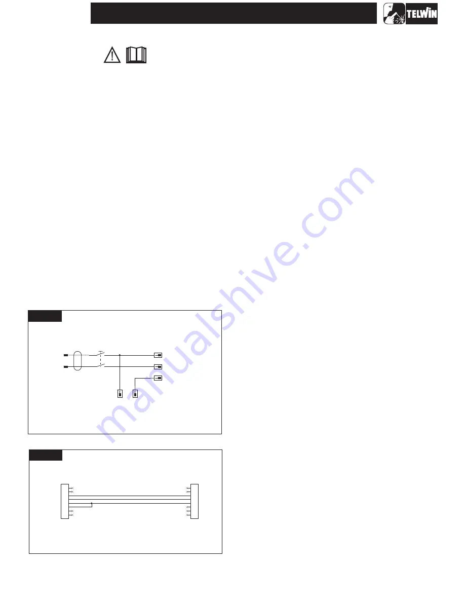
To carry out the low voltage tests on the machine, it is necessary to
use two special sets of test wiring that allow a 230Vac supply to
power the auxiliary transformer and by force some alarm signals
between the primary board and control board.
Follow the two electrical diagrams below to make the two sets of
wiring in figures A and B:
Every operation should be carried out in complete safety with the
power supply cable disconnected from the mains outlet.
-
undo the 12 screws fastening the 2 plastic shells (6 each) to the
front and back (
).
to extract the front plastic shell
it is necessary to disconnect all connectors on the control
board assembly. Fasten the control board assembly to the
metal front piece using its 4 screws and reconnect all the
connectors;
-
undo the 2 screws on the handle fastened to the top cover
(
;
-
undo the 14 screws fastening the top cover to the structure
(
);
-
pull gently outwards and slide out the top cover (
);
-
undo the 4 screws fastening the base to the structure (
);
-
separate the top metal structure from the base and place it on
the work bench.
the base should be removed if it is
necessary to reach the internal boards.
After completing the repairs, proceed in the reverse order to re-
assemble the machine and fasten the top cover and shells.
Using compressed air, carefully clean the power source
components since dirt is a danger to parts subjected to high
voltages and adversely affects the galvanic separation between
the primary and secondary boards.
It is important to be particularly
careful when cleaning the following parts:
Wiring for Aux Transf/Power supply/Aux Board
The following is a list of practical rules which must be strictly
adhered to if repairs are to be carried out correctly.
A) When handling the active electronic components, in particular
IGBT's and power DIODES, take elementary precautions for
electrostatic protection (such as wearing antistatic wristbands
or footwear, using antistatic working surfaces etc.).
B) To ensure the heat flow between the electronic components
and the dissipator, always place a thin layer of thermo-
conductive grease (e.g. COMPOUND GREASIL MS12)
between the contact zones.
C) The power resistors (should they require replacement) should
always be soldered at least 3 mm above the board.
D) If silicone is removed from some points on the boards it should
be re-applied.
N.B. Use only non-conducting neutral or oximic reticulating
silicones (e.g. DOW CORNING 7093). Otherwise, silicone that
is placed in contact with points at different potential (rheofores,
IGBT's etc.) should be left to reticulate before the machine is
tested.
E) The semiconductor devices should be soldered keeping below
the maximum temperature limits (usually 300°C for no more
than 10 seconds).
F) It is essential to take the greatest care at each disassembly
and assembly stage of the various machine parts.
G) Keep the small parts and other pieces that are dismantled from
the machine so as to be able to replace them in the reverse
order when re-assembling (damaged parts should never be
omitted but should be replaced, referring to the spare parts list
given at the end of this manual).
H) The boards (repaired when necessary) and the machine
wiring should never be modified without prior authorisation
from Telwin.
I)
For further information on machine specifications and
operation see the Instruction Manual.
1.0 Disassembling the machine
fig. 1A NOTE:
fig. 1A)
fig. 1B
fig.1B
fig. 1B
NOTE:
2.0 Cleaning inside the machine
To clean the electronic
boards we advise reducing the air pressure to prevent
damage to the components.
13
SUPERIOR PLASMA 90 HF
Figure B
JP5A
280373-1
1
2
3
4
5
6
7
8
JP5
280373-1
1
2
3
4
5
6
7
8
Figure A
230Vac
Alim.Aux
400V
Faston-M 6,3x0,8
SW1
Switch
0V
Faston-M 6,3x0,8
JP3B
Faston-M 6,3x0,8
L1
L2
230V
Faston-M 6,3x0,8
JP3A
Faston-M 6,3x0,8
Auxiliary transformer T3
Auxiliary power supply board
Auxiliary control wiring
Wiring auxiliary board side
Wiring control side
Содержание Superior Plasma 90 HF
Страница 7: ...SUPERIOR PLASMA 90 HF 7 General wiring diagram WIRING DIAGRAMS Wiring diagram input filter board...
Страница 8: ...SUPERIOR PLASMA 90 HF 8 Wiring diagram primary board power Wiring diagram primary board driver...
Страница 9: ...SUPERIOR PLASMA 90 HF Wiring diagram control board B Wiring diagram control board A 9...
Страница 10: ...SUPERIOR PLASMA 90 HF Wiring diagram control board D Wiring diagram control board C 10...
Страница 20: ...ILLUSTRATIONS SCREWS SCREW SCREWS TOP COVER SCREWS BOTTOM SCREWS 20 SUPERIOR PLASMA 90 HF SCREW SCREWS SCREWS...


