19.
Lift up on the Frame Section Retaining Latch and tip
the Frame Section into the locking position. Make sure the
Retaining Latch is firmly holding the Frame Section in place.
6
A
B
C
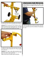
18.
To load the Frame Assembly, start by mounting the foot of
the Frame on the cart Base Section as shown. Angle “C” fits
OVER angle “B” and inside angle “A”.
A B
C
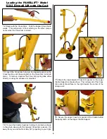
20.
Store the Tripod Base Assembly as shown above. Angle
“A” inserts beneath angle “C” while sliding over ridge “B”. The
Outer leg hinge points “D” will drop down into notch “E”.
D
E
21.
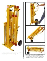
Lift the Tripod Retaining Latch and tip the Tripod base into
the locking position.


