background image

34

en | Assembly

2020-07 | 01 | F.01U.387.060

Customer Maintenance Manual

Bosch Security Systems, LLC

8.

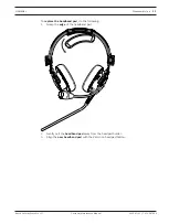
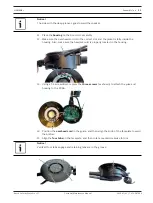
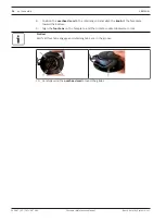
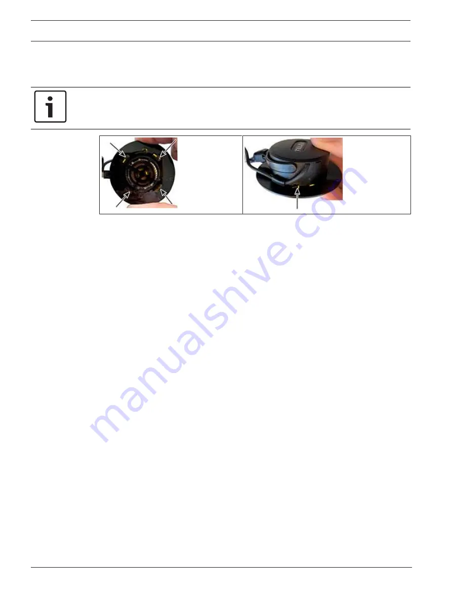
Position the 

overhead cord

 in the retaining clip and align the 

knob

 of the faceplate

toward the bottom.

9.

Align the 

four tabs

 on the faceplate, and then rotate counterclockwise to lock.

Notice!

Verify all four tabs engage and retaining tabs are in the groove.

10. Carefully wind the 

overhead cord

 around the glider.

Содержание AIRMAN8+ Series

Страница 1: ...AIRMAN8 AIRMAN8P 0210 DOUBLE SIDE ANR HEADSET AIRMAN8P 0211 DOUBLE SIDE ANR HEADSET en Customer Maintenance Manual...

Страница 2: ......

Страница 3: ...ation 15 5 4 2 Measure the resistance plug to PCBA 16 5 4 3 Validate the boom side PCBA 16 5 4 4 Validate the non boom side PCBA 16 5 5 ANR troubleshooting 17 5 5 1 Measuring ANR circuit voltages and...

Страница 4: ...4 en Record of revisions AIRMAN8 2020 07 01 F 01U 387 060 Customer Maintenance Manual Bosch Security Systems LLC 1 Record of revisions Revision No Revision Date Change Description 01 06 2020 Created...

Страница 5: ...el Number Part Description Part Number Quantity To find the proper address and phone number for your region please reference https telex com aviation solutions about telex aviation headsets contact te...

Страница 6: ...Airman 8 has improved durability intelligibility and comfort The Airman 8 is among the lightest Active Noise Reduction headsets on the market and one of only three FAA TSO C139a approved ANR headsets...

Страница 7: ...y Systems LLC Customer Maintenance Manual 2020 07 01 F 01U 387 060 Reference View 1 2 3 4 5 6 7 8 1 Headband Pad 2 Headband Pad Holder 3 Headset Gliders 4 Ear Cushions 5 Boom Rotator 6 Windscreen Micr...

Страница 8: ...1 ESP F01U347235 SPR F 01U 383 825 SPP Ear cushion Airman 8 2pcs 6 a b AIRMAN7 0904 ACC F 01U 313 419 CLOTHING CLIP 1 1 S F01U342113 SPR F 01U 342 113 7 b c AIRMAN7 0908 ACC F 01U 344 857 MIC PREFILT...

Страница 9: ...S F01U344918 SPR F 01U 344 918 OVER HEAD CABLE 1 1 24 S F01U344922 SPR F 01U 344 922 BOOM MIC ASSY AIRMAN 8 1 1 25 ESP F01U360396 SPR F 01U383 835 GLIDER YOKE ASSY AIRMAN 8 2 2 26 S F01U344924 SPR F...

Страница 10: ...ist and exploded view AIRMAN8 2020 07 01 F 01U 387 060 Customer Maintenance Manual Bosch Security Systems LLC 4 2 Exploded view 21 11 2 7 24 15 19 26 25 16 29 30 23 17 27 28 3 5 22 8 12 20 14 18 26 13...

Страница 11: ...boom microphone adjustment 5 1 Recommended maintenance schedule Notice Ear cushions headband pads and microphone windscreens are wear items For proper headset performance inspect and replace these ite...

Страница 12: ...l inspection Review all plastic parts for cracks or breaks To review plastic parts do the following Note any parts which need to be replaced Review all cables for obvious signs of damage to the insula...

Страница 13: ...est Sensitivity See ANR Troubleshooting But the microphone doesn t work Validate Mic PCBA Is Mic circuitry validated Replace Microphone Assembly Does ANR work Microphone Test Complete Adjust Microphon...

Страница 14: ...ests To test sensitivity of the microphone do the following 1 Calibrate an artificial mouth 2 Using the test circuit from the mic validation and TSO procedures measure the output of the headset microp...

Страница 15: ...sitivity Replace the Boom side Speaker Wires Check the solder points at the speaker and at the board Physically inspect speaker wires Replace the cable Measure Resistence of Speaker Test the PCBA Chec...

Страница 16: ...e place a probe at J13 4 Place the other probe at J14 If a signal is found the board is good and if no sound is heard from the speaker the speaker or wiring is bad Determine if the speaker needs to be...

Страница 17: ...he ANR Replace Resolder speaker Replace Boomside PCBA Validate Speaker Connections Replace Non boomside PCBA Replace Non boomside PCBA No No No No No No No No No No Does audio pass with no power Does...

Страница 18: ...probe at J11 If the measurement is near zero the switch is open 3 Move the ANR switch to the on position If the measurement is at 3 3Vdc 10 the switch is good If the measurement is anything else the s...

Страница 19: ...roughly 5 8 Replacing ear cushions and headband pads To ensure optimal product performance it is recommended you replace ear cushions and headband pads periodically every six months or sooner if neede...

Страница 20: ...ults the windscreen should be replaced Caution Do not use any liquid on the foam windscreen To remove the windscreen do the following 4 Grasp the microphone windscreen and gently pull away from the mi...

Страница 21: ...uch the plastic housing of the headset headphone with the soldering iron Notice Only disassemble parts that are necessary for the repair 6 1 Ear cushion replacement To ensure optimal product performan...

Страница 22: ...rity Systems LLC 6 2 Headband pad and headband pad replacement To replace the headband pads do the following 1 At one end of the headband pad holder carefully slide the holder from the headband cover...

Страница 23: ...stomer Maintenance Manual 2020 07 01 F 01U 387 060 To replace the headband pad do the following 1 Grasp the edge of the headband pad 2 Gently pull the headband pad away from the headpad holder 3 Align...

Страница 24: ...24 en Disassembly AIRMAN8 2020 07 01 F 01U 387 060 Customer Maintenance Manual Bosch Security Systems LLC 4 Firmly press the new headband pad into place...

Страница 25: ...yoke assembly from the headband assembly do the following 1 Use a fingernail to lift the bottom edge of the black plastic spacer 2 Swivel the black plastic spacer to the side and remove it from the as...

Страница 26: ...g a T 5 screwdriver remove three screws as shown 4 Remove the house and the yoke glider assembly 5 Using a T 5 screwdriver remove two screws as shown 6 Remove the PCBA 7 Using a soldering iron careful...

Страница 27: ...6 Non boom side disassembly To remove the speaker assembly and sleeve do the following 1 Pushing the two retaining cams simultaneously on the speaker assembly rotate the speaker faceplate approximate...

Страница 28: ...l Bosch Security Systems LLC 3 Remove the house and the yoke glider assembly 4 Using a T 5 screwdriver remove two screws as shown 5 Remove the PCBA 6 Using a soldering iron carefully disconnect the wi...

Страница 29: ...1 Solder the overhead cord to the PCBA J11 Red J12 Blue J9 White J10 Shield J17 Black 2 Solder the cable assembly to the PCBA 3 Thread the boom mic wires through the center hole 4 Using the two shorte...

Страница 30: ...n Red 7 Route the speaker wires through the housing and solder to the PCBA J13 Red J14 White 8 Route the overhead cord and the headset cord through the corresponding grooves provided on the boom 1 Pat...

Страница 31: ...d the jacket is fully inside the housing Also make sure the headset cord is properly located in the housing 13 Using a T 5 screwdriver replace the three screws as shown to attach the yoke and housing...

Страница 32: ...assembly To assemble the non boom side assembly do the following 1 Solder the overhead cord to the PCBA J11 Red J12 Blue J9 White J10 Shield J17 Black 2 Using the two shorter screws attach the PCBA to...

Страница 33: ...4 Route the speaker wires through the housing and solder to the PCBA 5 Place yoke on the housing Notice Take care to verify the orientation of the yoke because it does not rotate 360 6 Place the cove...

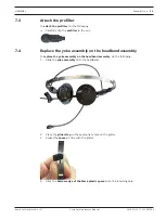
Страница 34: ...sition the overhead cord in the retaining clip and align the knob of the faceplate toward the bottom 9 Align the four tabs on the faceplate and then rotate counterclockwise to lock Notice Verify all f...

Страница 35: ...clip the prefilter to the mic 7 4 Replace the yoke assembly on the headband assembly To replace the yoke assembly on the headband assembly do the following 1 Slide the yoke assembly onto the headband...

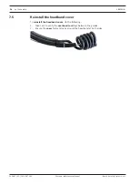
Страница 36: ...aintenance Manual Bosch Security Systems LLC 7 5 Reinstall the headband cover To reinstall the headband cover do the following 1 Take care to verify the overhead cord lays between the guides 2 Ensure...

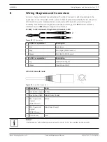
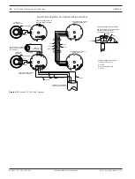
Страница 37: ...rotects against RFI Radio Frequency Interference and EMI Electromagnetic Interference PJ 068 PJ 055 Connector Diagram for Airman8 0210 1 2 Figure 8 1 PJ Connector 1 PJ 068 or equivalent Description Ti...

Страница 38: ...R WIRE OFF FLUSH SPEAKER NON BOOM SIDE SPEAKER BOOM SIDE PCBA F01U380742 ITEM 21 BOOM SIDE BOTTOM PCBA F01U380742 ITEM 21 BOOM SIDE TOP PCBA F01U380743 ITEM 20 NON BOOM SIDE TOP PCBA F01U380743 ITEM 2...

Страница 39: ...BER OFF FLUSH WITH JACKET THIS END ONLY J8 J18 J7 J5J6J2 J15 J1 PCBA F01U380743 ITEM 20 NON BOOM SIDE TOP J17 J10 J9 J12 J11 BLACK WHITE BLUE RED J14 J13 J18 J8 J7 J6 J5 J15 J1 J2 PCBA F01U380742 ITEM...

Страница 40: ...40 Wiring Diagrams and Connectors AIRMAN8 2020 07 01 F 01U 387 060 Customer Maintenance Manual Bosch Security Systems LLC...

Страница 41: ......

Страница 42: ...RTS 12000 Portland Avenue South Burnsville MN 55337 USA www rtsintercoms com Bosch Security Systems LLC 2020...

Отзывы: