18
en | Maintenance
2020-07 | 01 | F.01U.387.060
Customer Maintenance Manual
Bosch Security Systems, LLC
5.5.1
Measuring ANR circuit voltages and switch function
Notice!
This headset was designed, tested, and approved to FAA TSO C139a. The TSO requires the
headset meet the minimum performance specifications as defined in RTCA DO-214a. This
document and specifications listed here reference the test procedures and equipment used
as defined in these standards. Refer to the standard for details on how to perform individual
tests.
Notice!
Minimum attenuation requirements are not requirements of FAA TSO. To achieve the
minimum attenuation, Bosch approved test system is required.
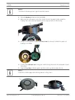
To
measure voltage and switch function on the boom side
, do the following:
1.
Verify the
headset main cable plugs are on
.
2.
Using a voltage meter, place the
ground probe at J10
.
3.
Place the
positive probe on TP14
.
If the measurement is 3.3Vdc, the power regulator is good. If the measurement is
anything other than 3.3Vdc ±10%, the power regulator is bad. Replace the board.
To
measure the switch functionality on the boom side
, do the following:
1.
If the regulator is good, verify the
ANR switch is in the off position
.
2.
Place the
positive probe at J11
.
If the measurement is near zero, the switch is open.
3.
Move the
ANR switch to the on position
.
If the measurement is at 3.3Vdc ±10%, the switch is good. If the measurement is anything
else, the switch is bad. Replace the board.
To
measure the fail-safe control logic for ANR
, do the following:
1.
Verify the
ANR switch is in the on position
.
2.
Place the
voltage meter probe at J12
on the boom-side.
If the measurement is greater than -6Vdc, the fail-safe logic is working properly. If the
measurement is anything below -6Vdc, the fail-safe logic is not working. Replace the
board.
To
measure voltage and switch function on the non-boom side
, do the following:
1.
If the boom side is good, place the
positive probe at J11 on the non-boom side
.
If the measurement is near 0, the switch is open
2.
Move the
ANR
switch to the on position
.
If the measurement is at 3.3Vdc ±10%, the switch is good. If the measurement is anything
else, the switch is bad. Replace the board.
To
measure the fail-safe control logic for ANR
, do the following:
1.
Verify the
ANR switch
is in the on position
.
2.
Place the
voltage meter probe at J12
on the non-boom-side
.
If the measurement is greater than -6Vdc, the fail-safe logic is working properly. If the
measurement is anything below -6Vdc, the fail-safe logic is not working. Replace the
board.
Notice!
For board replacement, contact Bosch ASA or a Bosch certified facility for replacement and
adjustment.
Содержание AIRMAN8+ Series
Страница 2: ......
Страница 41: ......
Страница 42: ...RTS 12000 Portland Avenue South Burnsville MN 55337 USA www rtsintercoms com Bosch Security Systems LLC 2020...

