background image

User Manual 


EAR99 technology subject to restrictions on copyrights page. 

Probe Compensation 

Proper compensation of the probe is required to assure amplitude accuracy 

of the waveform being measured by matching the probe to the 

oscilloscope’s input capacitance.  Compensation should be adjusted 

whenever the probe is connected to or transferred between oscilloscopes. 

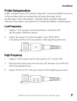
Low Frequency 

1.


Apply a 1 kHz square wave to the probe or connect to the 

oscilloscope’s calibrator output. 

2.


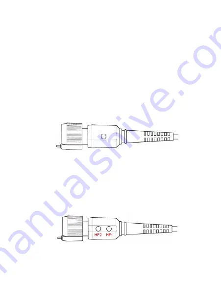
Adjust the single LF trimmer located on the PP023 BNC 

Compensation Box until you achieve a flat-topped square wave. 


High Frequency 

1.


Apply a 1 MHz square wave to the probe (< 0.7 ns rise-time). 

2.


Remove the plastic caps from the two, HF trimmers on the PP023 

BNC Compensation Box. 

3.


Adjust HF2 then HF1 until you achieve a flat-topped square wave. 


Содержание PP023

Страница 1: ...User Manual PP023 Passive Probe ...

Страница 2: ...yne LeCroy documentation materials is strictly prohibited Information contained herein is classified as EAR99 under the U S Export Administration Regulations Export reexport or diversion contrary to U S law is prohibited Teledyne LeCroy is a registered trademark of Teledyne LeCroy Inc Other product or brand names are trademarks or requested trademarks of their respective holders Information in thi...

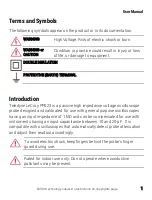
Страница 3: ...oduction Teledyne LeCroy PP023 is a passive high impedance voltage oscilloscope probe designed and calibrated for use with general purpose oscilloscopes having an input impedance of 1 MΩ and can be compensated for use with instruments having an input capacitance between 10 and 20 pF It is compatible with oscilloscopes that automatically detect probe attenuation and adjust their readout accordingly...

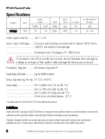
Страница 4: ...ategory ratings of the probe See voltage derating curve on p 3 Pollution Degree Pollution Degree 2 OperatingAltitude Upto3000meters Max Operating Temp 0 C to 50 C Humidity 5 to 95 RH 10 to 30 C 5 to 75 RH 30 to 40 C 5 to 50 RH above 40 C RH not controlled below 10 C AsdefinedinIEC EN61010 031 Seedefinitionsbelow Definitions MeasurementCategoryII CATII referstomeasurementsperformedoncircuitsdirectl...

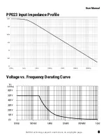
Страница 5: ...User Manual EAR99 technology subject to restrictions on copyrights page 3 PP023 Input Impedance Profile Voltage vs Frequency Derating Curve ...

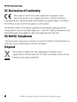
Страница 6: ...the European Communities IEC EN 61010 031 2015 Safety requirements for electrical equipment for measurement control and laboratory use Part 031 Safety requirements for handheld probe assemblies for electrical measurement and test EU RoHS2 Compliance The probe and accessories conform to the 2011 65 EU RoHS2 Directive inclusive of any modifications of said Directive Disposal The probe complies with ...

Страница 7: ...it Disconnect the probe input and reference lead from the test circuit before disconnecting from the oscilloscope Do not connect disconnect probes while connected to a voltage source Do not overload Do not apply any potential to the probe leads that exceeds the maximum rating of the probe Observe all terminal ratings on the oscilloscope before connecting Consult the oscilloscope product manual for...

Страница 8: ...ion Do not allow any portion of the probe to be submerged at any time Dry the probe and accessory thoroughly before attempting to make any voltage measurement Do not subject the probe to solvents or solvent fumes as these can cause deterioration of the probe body cables and accessories Service Refer all repairs to qualified service personnel Contact Teledyne LeCroy at the following address to arra...

Страница 9: ... probe is connected to or transferred between oscilloscopes Low Frequency 1 Apply a 1 kHz square wave to the probe or connect to the oscilloscope s calibrator output 2 Adjust the single LF trimmer located on the PP023 BNC Compensation Box until you achieve a flat topped square wave High Frequency 1 Apply a 1 MHz square wave to the probe 0 7 ns rise time 2 Remove the plastic caps from the two HF tr...

Страница 10: ...ighten the tips to avoid damaging the threads Ground Accessories The ground lead and the short collar are attached to the probe at the time of shipping To replace the ground lead with the swivel lead adapter unscrew the short collar from the probe and remove the ground lead Replace the short collar to hold the swivel lead adapter in place Alternatively the long collar can be pushed onto the probe ...

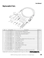
Страница 11: ... Trimmer Tool 1 6 PK5 2 5MM 105 Long Collar 1 7 PK5 2 5MM 106 IC Tip Insulators Black Brown Blue Green Gray 5 8 PK5 2 5MM 107 Tip Insulator 2 5mm 1 9 PK5 2 5MM 108 Probe Tip Cover 1 10 PK5 2 5MM 109 BNC Adapter 2 5mm 1 11 PK5 2 5MM 110 Swivel Ground Lead 1 12 PK5 2 5MM 111 Swivel Ground Lead Adapter 1 13 PK5 2 5MM 112 Ground Spring 1 14 PK5 2 5MM 113 PCB Adapter 1 15 PK5 2 5MM 114 Spring Tip 1 16 ...

Страница 12: ...anty Teledyne LeCroy at its option will either repair or replace any assembly returned within the warranty period to the Customer Service Department of an authorized service center However this will be done only if the product is determined by Teledyne LeCroy s examination to be defective because of workmanship or materials and the defect is not caused by misuse neglect accident abnormal condition...

Отзывы: