background image

Troubleshooting and Service 

Teledyne API – Model T108 Addendum to T100 Manual 


18 

07268C DCN8258 


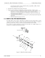
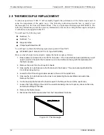
2.5  THERMOCOUPLE REPLACEMENT 

Continuous operation at 1000 ºC will eventually degrade the performance of the thermocouple used to 

sense the temperature of the  quartz oven.  The following instructions describe how to install a new 

thermocouple into the Converter Heater Block.  This is a replacement thermocouple (KIT000255). The 

following instructions provide the necessary information to remove the existing thermocouple and replace 

it with the new one supplied in Kit 255. 
You will need the following tools:


Nutdriver, 

5

/

16


Nutdriver, 

11

/

32


Diagonal Cutter 


Philips head Screwdriver #2 

You will need to obtain the following replacement parts kit from TAPI: 


KIT000255 (AKIT, Retrofit, 501TS, TC Type S RPLCMN)


Once you have the right tools and parts, replace the thermocouple as follows: 

1.  Ensure power is removed from the 501TS Converter.  If the Converter has been operational you will 

need to wait for 2 hours for the Converter oven to cool before continuing with the replacement of 

the thermocouple. 

2.  Remove the cover from the Converter chassis. 
3.  Unscrew the (4) nuts that secure the front panel to the chassis.  They are located just behind the 

Front Panel along the top. 

4.  Lower the Front Panel to gain easier access to the end of the quartz tube. 
5.  Unscrew the (3) nuts that secure the inner cover protecting the Heater Block and quartz tube.  

Remove this cover. 

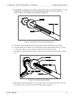
6.  Cut the tie-wrap that secures the thermocouple to the fitting at the end of the quartz tube.   
7.  Loosen the Teflon fitting at the end of the quartz tube taking care not to put any stress on the tube, 

and slide the fitting off the tube. 

8.  Remove the thermocouple. 
9.  Disconnect the thermocouple wires from the Temperature Controller. 


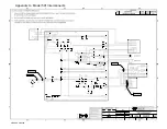
Figure 2-2. Thermocouple 

Содержание T108 Series

Страница 1: ...yzer when used in conjunction with both the T100 manual PN 06807 and the T100U addendum PN 06840 TELEDYNE API TAPI 9970 Carroll Canyon Road SAN DIEGO CA 92131 1106 USA Toll free Phone 800 324 5190 Pho...

Страница 2: ......

Страница 3: ...be used in conjunction with the T100 operation manual It also supports the T108U analyzer when used in conjunction with both the T100 manual and the T100U manual Note We recommend that all users read...

Страница 4: ...Teledyne API Model T108 Addendum to T100 Manual ii 07268C DCN8258 This page intentionally left blank...

Страница 5: ...ECORD 21 List of Figures Figure 1 1 Basic Pneumatics Configuration 7 Figure 1 2 Pneumatics with IZS Permeation Tube Option 8 Figure 1 3 Pneumatics with 702 Calibrator Option 9 Figure 1 4 501TS Convert...

Страница 6: ...Teledyne API Model T108 Addendum to T100 Manual iv 07268C DCN8258 This page intentionally left blank...

Страница 7: ...ciency 20 ppmv Minimum Conversion Efficiency In CO2 matrix H2S COS CS2 98 90 Least Discernible Level LDL See T100 Manual Operating Converter Temperature 1000 oC Maximum Converter Temperature 1050 oC P...

Страница 8: ...yzer where the SO2 and converted compounds are analyzed as SO2 1 3 CONFIGURATIONS There are three configurations available the standard analyzer and two with options Configuration Description Standard...

Страница 9: ...Teledyne API Model T108 Addendum to T100 Manual Introduction 07268C DCN8258 7 M501 TS Figure 1 1 Basic Pneumatics Configuration...

Страница 10: ...Introduction Teledyne API Model T108 Addendum to T100 Manual 8 07268C DCN8258 M501 TS Figure 1 2 Pneumatics with IZS Permeation Tube Option...

Страница 11: ...Teledyne API Model T108 Addendum to T100 Manual Introduction 07268C DCN8258 9 M501 TS Figure 1 3 Pneumatics with 702 Calibrator Option...

Страница 12: ...een preset in the temperature controller The heater temperature is sensed by a Type S distinguished from other thermocouple types by its wire colors red and black Platinum Rhodium thermocouple probe i...

Страница 13: ...Teledyne API Model T108 Addendum to T100 Manual Introduction 07268C DCN8258 11 Figure 1 4 501TS Converter Chassis Layout...

Страница 14: ...matic connections are shown in Figure 1 5 Connection to the TS analyzer must be made with Teflon tubing Connect the sample inlet to the labeled fitting The sample exhaust must be routed to a well vent...

Страница 15: ...of the SO2 analyzer This unit has some unique operating characteristics and calibration procedures detailed below The basic purpose of this instrument is to analyze CO2 sample gas for sulfur containi...

Страница 16: ...librator be used to mix zero gas CO2 into the cal gas stream making the final calibration gas mostly CO2 1 7 TS AND ZERO AIR SCRUBBERS There are two charcoal scrubbers in the analyzer chassis of the T...

Страница 17: ...iled Check that its leads are securely connected to the wiring block at the back of the controller Also check the thermocouple resistance across the leads for opens or shorts TS ANALYZER UNSTABLE Leak...

Страница 18: ...ttings at each end of the tube 5 Carefully slide the tube out of the heater the ceramic bushings at each end of the heater are very fragile 6 Slide the new tube into the heater and re connect the fitt...

Страница 19: ...pproximately 5 of Full Scale is observed Note the Thermal Converter temperature at this point Verify that the converter efficiency does not drop by 5 until the temperature has dropped by at least 40 o...

Страница 20: ...ou have the right tools and parts replace the thermocouple as follows 1 Ensure power is removed from the 501TS Converter If the Converter has been operational you will need to wait for 2 hours for the...

Страница 21: ...ouple 11 The thermocouple should slide into the Heater Block and into the indentation of the quartz 12 Align the thermocouple with this cavity and carefully push the thermocouple all the way into the...

Страница 22: ...A leak check should be performed on the Converter to verify that all connections are leak free If a leak is detected the leak should be resolved before continuing 19 Install the inner cover of the Hea...

Страница 23: ...e 3 3 Table 3 1 Final Test and Calibration Values for T108 TEST Parameters Observed Value Units Acceptable Value RANGE PPB 50 20 000 STABIL PPB 0 0 2 PRESS HG 24 35 SAMP FL CC MIN 500 700 w CO2 PMT mV...

Страница 24: ...b with zero air STAB2 PPB 0 1 ppb with zero air PRESS HG ambient 2 SAMPLE FL CC MIN 650 cm3 min 10 PMT mV 20 TO 150 mV with zero air UV LAMP mV 2000 4800 STR LGT PPB 25 DRK PMT MV 200 325 DRK LMP MV 5...

Страница 25: ...s Parameter Observed Value Units Nominal Range Sample Flow w CO2 cc min 500 700 Sample Flow w Air cc min 400 600 Sample Press w CO2 HG 24 27 IZS Purge Flow cc min 50 10 H2S Conversion Efficiency Expec...

Страница 26: ...Appendix A Model 501 Interconnects 07268C DCN8258...

Отзывы: