09419A DCN8342
Teledyne API Model 480L O
3
Monitor User Manual
51
(Figure 7-3). Slowly turn the pot and observe the REF value on the display. The
target adjustment range is as high as possible within the range of 800-1150 mV.
6. Close front panel and observe REF value on display for a couple minutes to verify
that it does not drift out of the adjustment range.
7.7 UV LED REPLACEMENT
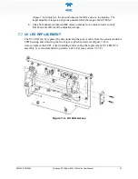
The UV LED can be replaced by disconnecting the power cable from the sensor module’s
LED housing and removing the two larger socket head screws (Figure 7-4) to
remove/replace the LED. After installing and securing the replacement UV LED PCA
assembly, it is recommended to perform a Zero Cal (see section 5.2.3.2).
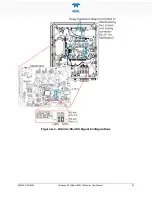
Figure 7-4. UV LED Access

