


34
Teledyne API Model 465H O
3
Monitor User Manual
06161H DCN7969
7.2.5.
DIAG Menu
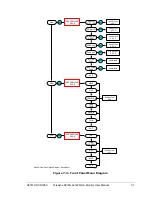
The DIAG menu (See Figure 7-2 and Figure 7-3) contains functions that are useful for
calibration and I/O testing.
7.2.5.1.
Analog Step-Test
When placed in this mode, the instrument will automatically step the analog output
through 5 points from 0 to 100 % and display the current value on the front panel. The
operator can suspend the automatic cycling and manually control the stepping by pressing
either one of the
UP
/
DOWN
arrow buttons. To resume automatic cycling, exit the
function by pressing
CFG
and re-enter by pressing
ENT
.
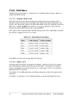
The 5 points will correspond to the following analog output values depending on whether
the output is configured for 0-5V or 4-20mA:
Table 7-5: Analog Step Test Values
Point
0-5V Output
4-20 mA Output
0%
0.00 V ± 0.02
4 mA ± 0.02
25%
1.25 V ± 0.02
8 mA ± 0.02
50%
2.50 V ± 0.02
12 mA ± 0.02
75%
3.75 V ± 0.02
16 mA ± 0.02
100%
5.00 V ± 0.02
20 mA ± 0.02
Press
CFG
to exit from the Analog Step-Test function.
7.2.5.2.
Signal I/O
The Signal I/O menu allows the operator to manually control the various relay outputs
and control inputs available on the rear panel of the 465H. This function is useful for
testing or debugging external control systems (i.e. data-loggers or PLC’s) to which the
instrument may be connected.
See Section 4.5 for additional details on making connections to these I/O signals on the
rear panel.
See Figure 7-2 and Figure 7-3 for additional details on entering the Signal I/O menu.


