background image


USER MANUAL 

MODEL 465H 

OZONE MONITOR 

Teledyne API (TAPI) 

9970 Carroll Canyon Road 

San Diego, CA 92131-1106 


Toll-Free: 800-324-5190 

Phone:    +1 858-657-9800 

 FAX:   +1 858-657-9816 

Email: 

[email protected]


Website: 

http://www.teledyne-api.com/


©2007-2018 TAPI 

06161H DCN7969 

Teledyne API 

21 August 2018


Содержание 465H

Страница 1: ...e API TAPI 9970 Carroll Canyon Road San Diego CA 92131 1106 Toll Free 800 324 5190 Phone 1 858 657 9800 FAX 1 858 657 9816 Email api sales teledyne com Website http www teledyne api com 2007 2018 TAPI...

Страница 2: ......

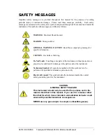
Страница 3: ...information CAUTION Hot Surface Warning Do Not Touch Touching some parts of the instrument without protection or proper tools could result in damage to the part s and or the instrument Technician Sym...

Страница 4: ...ements sp cifiques MISE EN GARDE Surface chaude Ne pas toucher Toucher certaines parties de l instrument sans protection ou sans les outils appropri s pourrait entra ner des dommages aux pi ces ou l i...

Страница 5: ...ment provided but not manufactured by TAPI is warranted and will be repaired to the extent and according to the current terms and conditions of the respective equipment manufacturer s warranty Product...

Страница 6: ...iv Teledyne API Model 465H O3 Monitor User Manual 06161H DCN7969 THIS PAGE IS INTENTIONALLY LEFT BLANK...

Страница 7: ...g Flow Control Assemblies 18 4 4 2 Ozone Inlet Connection 19 4 4 3 Zero Gas Connection 19 4 4 4 Exhaust Connection 19 4 5 ELECTRICAL I O CONNECTIONS 21 4 5 1 Location of I O Connectors in the NEMA Con...

Страница 8: ...ARTICULATE FILTER 50 9 4 UV LAMP ADJUSTMENT 51 9 5 UV LAMP REPLACEMENT 52 9 6 REPLACING THE AUTO ZERO VALVE 52 9 7 CONFIGURING THE ANALOG OUTPUT 53 9 8 CLEANING EXTERIOR SURFACES OF THE 465H 54 9 9 BO...

Страница 9: ...Pneumatic Diagram 58 Figure 10 2 Interconnect Diagram 59 TABLES Table 4 1 465H Ventilation Clearances NEMA Version 13 Table 4 2 465H Ventilation Clearances Rack Mount Version 14 Table 4 3 Status Outp...

Страница 10: ...ostics to allow maximum uptime We at Teledyne API will be pleased to provide you with any support required so that you may utilize our equipment to the fullest extent Our full time technical support d...

Страница 11: ...e Range 3 0 30 0 psig Sample Flow Rate 0 2 2 0 LPM Humidity Range 10 90 RH non condensing Temperature Range 5 45o C Dimensions H x W x D 5 22 x 19 0 x 15 3 3U RETMA Panel 133 mm x 483 mm x 388 mm In N...

Страница 12: ...for measurement control and laboratory use CE 2006 95 EC Low Voltage Directive 2 2 2 EMC EN 61326 1 IEC 61326 1 Class A Emissions Industrial Immunity EN 55011 CISPR 11 Group 1 Class A Emissions FCC 4...

Страница 13: ...ne absorption coefficient L path length 3 O C concentration of ozone in parts per million T sample temperature in Kelvin P pressure in pounds per square inch absolute As can be seen the concentration...

Страница 14: ...light is converted into a voltage by the detector preamp module The voltage is converted into a number by a high resolution A D analog to digital converter The digitized signal along with the other v...

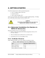
Страница 15: ...suitable vent outside the monitor area 4 1 Mechanical Installation for Monitors in NEMA 4X Enclosures Mount the enclosure securely to a vertical surface Figure 4 1 shows the locations of the four moun...

Страница 16: ...tor or to be mounted in a standard 19 RETMA instrumentation rack For rack installations the four mounting feet should be removed from the bottom of the monitor 4 2 1 Ventilation Clearance When install...

Страница 17: ...sures Use appropriate wiring rated for this type of equipment ensuring that it meets local and national safety and building requirements Ensure that overcurrent protection is used a 5 A circuit breake...

Страница 18: ...shown in the Figure below Do not connect the earth ground wire directly to the PCB connector on the mainboard PCB b Line Black Connect the Line wire to the connector on the mainboard PCB labeled Line...

Страница 19: ...ncluding the instrument serial number and software revision When the instrument first powers up the display will show xxxx indicating that the instrument is in start up mode waiting for the UV detecto...

Страница 20: ...se Flow Control Assemblies if an adjustable flow control is desired Use only needle valves that are constructed of materials compatible with high concentrations of ozone such as stainless steel and Te...

Страница 21: ...on 4 4 1 on the Zero Gas Inlet Zero Gas supply pressure should be regulated between 5 and 30 psig 4 4 4 Exhaust Connection Connect a OD vent line to the Exhaust fitting on the rear panel This line mus...

Страница 22: ...20 Teledyne API Model 465H O3 Monitor User Manual 06161H DCN7969 Figure 4 5 Rear Panel Electrical I O Connections Figure 4 6 NEMA Electrical I O Connections...

Страница 23: ...trument See Figure 4 6 for their location Connection to these terminals is usually made via a conduit connection to the NEMA enclosure A standard conduit penetration may be added to one of the walls o...

Страница 24: ...us Outputs There are four instrument status outputs located at the General I O connector These status outputs mirror the state of the four diagnostic LED s on the front panel If any of these status ou...

Страница 25: ...relays are dry contact type form C SPDT relays with Normally Open N O Normally Closed N C and Common COM contacts The relays are capable of driving loads of up to 250VAC 5A For maximum contact life t...

Страница 26: ...e three COM pins on the General I O connector See Section 8 2 for additional details When using RS232 a 9 pin serial cable TAPI P N WR77 can be used to connect the instrument to a standard PC personal...

Страница 27: ...The typical lifetime is about 2 3 years The lamp output will steadily decrease until lamp adjustment can no longer be performed The Check Lamp warning LED will tell the operator when this adjustment...

Страница 28: ...1 Rack Mount Slides Rack mount slides can be attached to the sides of the instrument allowing it to slide completely out of a RETMA rack facilitating maintenance activities 6 2 Ethernet MODBUS TCP IP...

Страница 29: ...t indicating the current measurement units If none of these indicators are backlit then the display is in Menu mode or Startup mode and is not displaying the concentration If the display is in Menu mo...

Страница 30: ...ton has no effect when the alarms are configured for non latching operation See Sections 7 2 3 and 4 5 4 for additional details on concentration alarms 7 1 4 Status LED s There are four Status LED s o...

Страница 31: ...avigation Basics 1 Press CFG from Concentration mode to enter Menu mode 2 Once in Menu mode CFG will move backwards one level in the menu structure and ENT will move forward 3 Each menu level contains...

Страница 32: ...30 Teledyne API Model 465H O3 Monitor User Manual 06161H DCN7969 Figure 7 2 Front Panel Menu Diagram...

Страница 33: ...S N ENT COMM ADDRESS REV See Section 6 2 5 2 ENT See Section 6 2 6 MEMORY RESET See Section 6 2 5 3 ENT FLOW ZERO CAL See Section 6 2 5 4 ENT SPAN CAL See Section 6 2 5 5 ENT SEE PREVIOUS PAGE SEE PRE...

Страница 34: ...are triggered The options available Table 7 3 Alarm Configuration Properties Property Meaning Default Value Range HI ALARM HI alarm trigger value 1 00 WT 1 00 g Nm3 0 02 25 0 0 02 400 g Nm3 HIHI ALARM...

Страница 35: ...o trigger alarms 5 1 20 BC FILT SIZE Boxcar filter s length for concentration filter Higher values will smooth out the concentration readings but will also increase the response time 30 1 30 FLOW SWIT...

Страница 36: ...he following analog output values depending on whether the output is configured for 0 5V or 4 20mA Table 7 5 Analog Step Test Values Point 0 5V Output 4 20 mA Output 0 0 00 V 0 02 4 mA 0 02 25 1 25 V...

Страница 37: ...be adjusted every 720 minutes If the zero calibration is disabled then manual calibration is necessary based on the customer s applications For normal applications the Auto Zero is not necessary The z...

Страница 38: ...ion is successful the display will return to the concentration menu and the monitor reading should change adjust to read very close to the target value If the calibration cannot be performed an OUT OF...

Страница 39: ...arameters Parameter Meaning Units Normal Range MEAS UV detector reading measure cycle mV 250 1230 REF UV detector reading reference cycle mV 250 1230 PRESSURE Sample pressure psia 9 0 18 0 LAMP TEMP U...

Страница 40: ...2 3 7 2 4 and 7 2 5 however the CONFIG menu just contains instrument specific information 7 3 Analog Output The 465H provides an analog output of the current O3 reading on the rear panel see Section 4...

Страница 41: ...t can also be performed over the COM port 8 2 Changing COM Port Hardware Configuration WARNING Electrical Shock Hazard The operations outlined in this section are to be performed by qualified maintena...

Страница 42: ...e portion of the COM port configuration will now automatically be completed after the next instrument boot up Close Indicated Positions Only RS232 ETHERNET RS485 7 6 5 4 3 2 1 SW3 10 9 8 RS232 Configu...

Страница 43: ...connector Only one of these connections should be used the other must be left un connected Table 8 1 below details the pinouts of these two connectors Table 8 1 RS 232 Connector Details Function DB 9...

Страница 44: ...the DB 9 connector labeled RS232 485 or to the three COM pins on the General I O connector Table 8 3 below details the pinouts of these two connectors Table 8 3 RS 485 Connector Details Function DB 9...

Страница 45: ...mple network can easily be constructed for this purpose by using a small broadband router commonly used for home networks The 465H and a PC can then be connected to the router and the router s DHCP se...

Страница 46: ...ltiple devices are shown the correct one can be determined by matching the Hardware Address shown with the address printed on the label of the Ethernet module in the 465H 8 5 4 Manually Assigning a St...

Страница 47: ...selected unit 8 From the Tools menu click the Ping button The results display in the Status window Click the Clear Status button to clear the window so you can ping the device again 9 Click the Close...

Страница 48: ...Inverse 0 32 21 Sensor Measure Value mV Float Inverse 0 32 23 Sensor Pressure Value mV Float Inverse 0 32 25 Sensor Gas Temperature K Float Inverse 0 32 27 Sensor UV Lamp Temperature o C Float Inverse...

Страница 49: ...uggested maintenance procedures and intervals for ensuring the 465H continues to operate accurately and reliably Table 9 1 Maintenance Schedule Maintenance Item Recommended Interval Section Replace pa...

Страница 50: ...O3 Monitor User Manual 06161H DCN7969 9 2 Instrument Layout Figure 9 2 show the instrument layout of the 465H These figures will be referenced in the procedures that follow Figure 9 1 Instrument Layou...

Страница 51: ...06161H DCN7969 Teledyne API Model 465H O3 Monitor User Manual 49 Figure 9 2 Instrument Layout NEMA Configuration...

Страница 52: ...the four washers and the sample filter body from the sample filter base 7 Remove the o ring and inspect for any cracks or deformities If there are no cracks or deformities place the o ring back in th...

Страница 53: ...hould be a scrolling display similar to REF XXXX MV See Section 7 2 for details on menu navigation 5 While observing the REF value on the display slowly turn the pot to adjust the value The target adj...

Страница 54: ...UV lamp housing see Figure 9 1 or Figure 9 2 4 Unplug the lamp power cord from the connector labeled J18 on the mainboard PCA 5 Carefully slide the lamp out of housing 6 Install the new lamp seating...

Страница 55: ...1 R62 R61 R29 SW1 K4 K5 K7 K8 K9 K10 C62 CPU ALIVE D14 R22 R25 R27 Q2 R54 PR3 PR4 C65 C70 J11 PR2 PR1 R2 SW2 SW4 J5 U29 R60 R63 DCP010515 U21 VR7 LM7805 VR2 C56 C46 C58 Y1 R1 R48 R42 R47 R51 R37 R38 R...

Страница 56: ...er setup hardware and software described in the following sections 9 9 1 Boot Loader Hardware Setup Verify that the instrument is configured for an RS 232 connection See Section 8 2 for details on cha...

Страница 57: ...ppb ppm ugm 05498 01_XX HEX for ppb ppm pphm The firmware loader is available on Teledyne API s website at http www teledyne api com software 1 Install the firmware loader software onto a PC 2 Verify...

Страница 58: ...ment s current firmware to the selected HEX file see Section 9 9 2 step 5 and confirms whether or not the files are a match 1 Press Verify The screen will display Wait for boot loader 2 When the scree...

Страница 59: ...ul upload a message Verify flash error is displayed If a Verify flash error occurs ensure that the correct PC COM port is selected for the instrument see Section 9 9 2 step 4 NOTE A verification proce...

Страница 60: ...e useful when performing certain troubleshooting activities 10 1 1 Pneumatic Diagram Figure 10 1 is a pneumatic diagram that can be referenced when performing troubleshooting on the monitor Flow Contr...

Страница 61: ...SWITCH OPTIONAL 15V SW0000051 POWER SWITCH CIRCUIT BREAKER CN0000073 IEC TYPE POWER ENTRY MODULE RACK MOUNT VERSION ONLY J13 VALVE 05313 0100 DISPLAY PCA J2 J4 J8 J16 J20 J17 J7 03484 XXXX SENSOR ASSY...

Страница 62: ...n Reference 125 0 mV Measure 1230 0 mV Yes 2 Invalid Reading Off O3 Concentration 0 5 WT O3 Concentration Analog Range No 3 Check Lamp Off Reference 250 0 mV No 4 Pneumatic Error Off Pressure 9 0 psia...

Страница 63: ...where UV Lamp Adjustment See Section 9 4 should be made at the next convenient opportunity Note that this is a non critical warning and immediate service is not required However if the UV Lamp intens...

Страница 64: ...between Ground TP3 and the pressure signal TP8 This voltage should read between 1 15 1 34 V when measuring ambient atmospheric pressure If the voltage is outside this range then the pressure sensor sh...

Страница 65: ...ry Calibration The 465H is calibrated to internal Teledyne API TAPI calibration standards to shipment A calibration certificate for your instrument can be purchased from TAPI if required TAPI also rec...

Страница 66: ...l does not solve your problems technical assistance may be obtained from Teledyne API Technical Support 9970 Carroll Canyon Road San Diego California 92131 1106 USA Toll free Phone 800 324 5190 Phone...

Отзывы: